Dodge Dakota (ND). Manual — part 1130
ASSEMBLY-SHIFT MOTOR/MODE SENSOR
DESCRIPTION
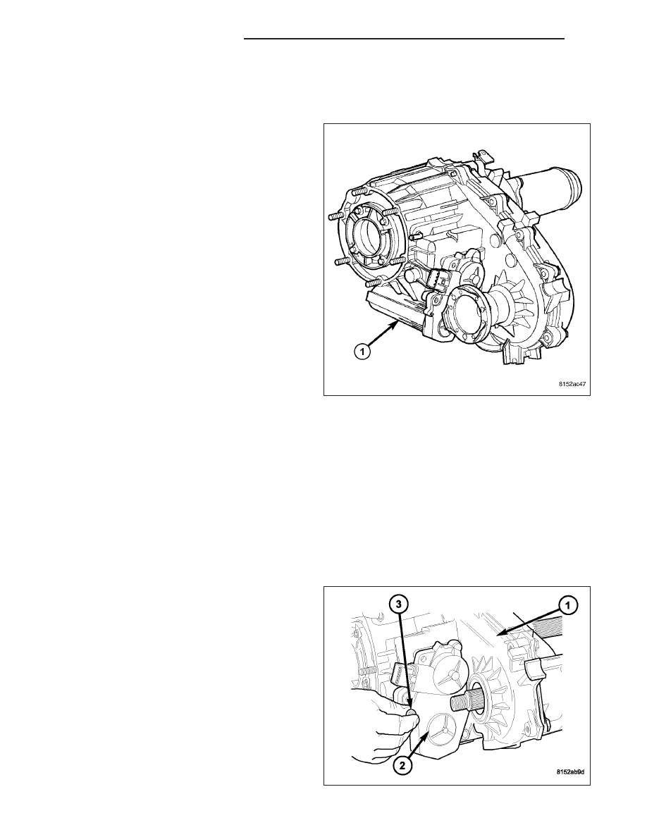
The shift motor (1) is an electromechanical device
consisting of a DC permanent magnet motor, gear
train, and an analog position sensor. The shift motors’
overall function is to move and lock a gear that moves
the mode and range forks found in the transfer case.
This allows the transfer case to be shifted electrically
to multiple operating positions (4HI, 2WD, N (neutral),
and 4LO). The operating current of the shift motor
under stall conditions is 30 amps maximum at 72° F
with 13.5 volts, at the motor leads.
OPERATION
Shifting in the transfer case occurs when a Pulse Width Modulated (PWM) voltage is supplied to the shift motor by
the Front Control Module (FCM). A linear analog position sensor located inside the shift motor, provides the FCM
with the motors’ angular, rotational position. With this information, the FCM continuously knows the motors’ position,
and therefore allows it to accurately control the motors’ operation, including voltage polarity which is used to control
motor direction.
REMOVAL
NOTE: New shift motor assemblies are shipped in the 2WD/AWD position. If a new shift motor assembly
must be installed, it will be necessary to shift the transfer case to the 2WD/AWD position prior to motor
installation.
1. Raise the vehicle on a suitable hoist.
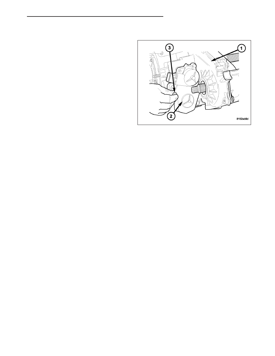
2. Disengage the wiring connector from the shift
motor and mode sensor assembly.
3. Remove the bolts (3) holding the shift motor and
mode sensor assembly (2) onto the transfer case
(1).
4. Separate the shift motor and mode sensor assem-
bly (2) from the transfer case (1).
21 - 912
TRANSFER CASE - NV233
ND
INSTALLATION
1. Verify that the shift motor o-ring is clean and prop-
erly positioned inside the machined o-ring groove
of the shift motor.
2. Add high temperature grease between the actuator
and the transfer case mating surface for sealing
purposes.
NOTE: Verify that the shift motor position and sec-
tor shaft orientation are aligned. It may be neces-
sary to manually shift the transfer case if the shift
motor and sector shaft are not aligned.
3. Position the shift motor and mode sensor assembly
(2) onto the transfer case (1).
4. Install the bolts (3) to hold the assembly (2) onto
the transfer case (1). Tighten the bolts to 16-24
N·m (12-18 ft.lbs.).
CAUTION: If the original shift motor and mode sensor assembly bolts are reused, be sure to use Mopar
T
Lock & Seal or Loctite™ 242 to replenish the lock patch material originally found on the bolts
5. Engage the wiring connector to the shift motor and mode sensor assembly.
6. Refill the transfer case as necessary.
7. Lower vehicle and verify transfer case operation.
ND
TRANSFER CASE - NV233
21 - 913

SWITCH-TRANSFER CASE SELECTOR
DESCRIPTION
The selector switch assembly is mounted in the right side of the vehicle’s Instrument Panel (IP) and consists of a
rotary knob connected to a resistive network for the mode and range shift selections. Also located in this assembly
is a recessed, normally open momentary switch for making shifts into and out of transfer case NEUTRAL. A pen, or
similar instrument, is used to make a NEUTRAL shift selection, thus reducing the likelihood of an inadvertent shift
request.
OPERATION
As the position of the selector switch varies, the resistance between the Mode Sensor supply voltage pin and the
Mode Sensor output will vary. Hardware, software, and calibrations within the Front Control Module (FCM) are pro-
vided that interpret the selector switch resistance as given in the table below: SELECTOR SWITCH INTERPRETA-
TION
SELECTOR SWITCH INTERPRETATION
Required Interpretation
Resistance Range (ohms)
Shorted
<150
2WD+NEUTRAL
176-200
4HI+NEUTRAL
190-216
4LO+NEUTRAL
199-226
2WD (Default)
1159-1287
4HI
2259-2503
4LO
4820-5334
Open/Diagnostic
>19K
The internal structure and function of the selector switch is such that the connection is made to the Open/Diagnostic
resistor before the connection to the individual position resistors is broken. Because of this characteristic, if the
resistance between the Mode Sensor supply voltage pin and the Mode Sensor output pin is >19k ohms, the position
resistor is open.
21 - 914
TRANSFER CASE - NV233
ND
TRANSFER CASE - NV244
TABLE OF CONTENTS
page
page
TRANSFER CASE - NV244
. . . . . . . . . . . . . . . . . . . . . . . . 915
. . . . . . . . . . . . . . . . . . . . . . . . . . 916
DIAGNOSIS AND TESTING - TRANSFER
. . . . . . . . . . . . . . . . . . . . . . . 917
. . . . . . . . . . . . . . . . . . . . . . . . . . . . 918
. . . . . . . . . . . . . . . . . . . . . . . . 919
. . . . . . . . . . . . . . . . . . . . . . . . . . . 933
. . . . . . . . . . . . . . . . . . . . . . . . . . 933
. . . . . . . . . . . . . . . . . . . . . . . . . . . 935
. . . . . . . . . . . . . . . . . . . . . . . . 954
SPECIFICATIONS - TRANSFER CASE -
. . . . . . . . . . . . . . . . . . . . . . . . . . . . . 955
FLUID
STANDARD PROCEDURE - FLUID DRAIN AND
. . . . . . . . . . . . . . . . . . . . . . . . . . . . . 958
SENSOR-MODE
. . . . . . . . . . . . . . . . . . . . . . . . 958
. . . . . . . . . . . . . . . . . . . . . . . . . . 958
SEAL-FRONT OUTPUT SHAFT
. . . . . . . . . . . . . . . . . . . . . . . . . . . . 960
. . . . . . . . . . . . . . . . . . . . . . . . 960
BUSHING/SEAL-REAR RETAINER
. . . . . . . . . . . . . . . . . . . . . . . . . . . . 961
. . . . . . . . . . . . . . . . . . . . . . . . 961
ASSEMBLY-SHIFT MOTOR/MODE SENSOR
. . . . . . . . . . . . . . . . . . . . . . . . 962
. . . . . . . . . . . . . . . . . . . . . . . . . . 962
. . . . . . . . . . . . . . . . . . . . . . . . . . . . 962
. . . . . . . . . . . . . . . . . . . . . . . . 963
SWITCH-TRANSFER CASE SELECTOR
. . . . . . . . . . . . . . . . . . . . . . . . 963
. . . . . . . . . . . . . . . . . . . . . . . . . . 963
TRANSFER CASE - NV244
DESCRIPTION
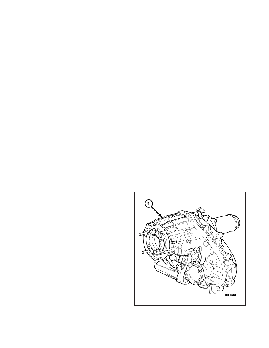
The NV244 (1) is an electronically controlled full and
part-time transfer case with no two wheel drive oper-
ation.
A differential in the transfer case is used to control
torque transfer to the front and rear axles. A low range
gear reduction system provides increased low speed
torque capability for off road operation. The low range
provides a 2.72:1 reduction ratio.
The geartrain is mounted in two aluminum case
halves attached with bolts. The mainshaft front and
rear bearings are mounted in aluminum retainer hous-
ings bolted to the case halves.
ND
TRANSFER CASE - NV244
21 - 915
Нет комментариевНе стесняйтесь поделиться с нами вашим ценным мнением.
Текст