Dodge Dakota (ND). Manual — part 1129
FLUID
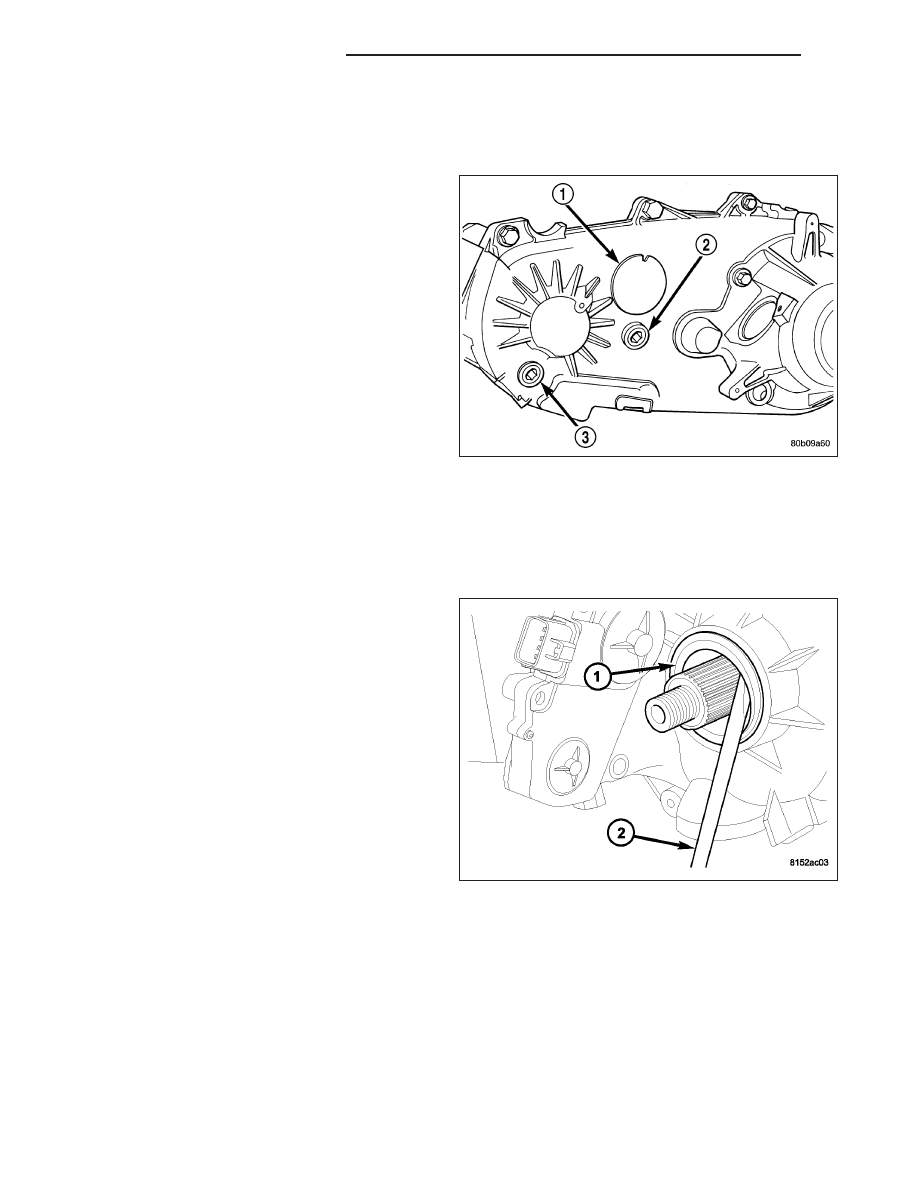
STANDARD PROCEDURE - FLUID DRAIN AND REFILL
The fill (2) and drain (3) plugs are both in the rear
case.
1. Raise vehicle.
2. Position drain pan under transfer case.
3. Remove drain and fill plugs and drain lubricant
completely.
4. Install drain plug. Tighten plug to 20-34 N·m (15-25
ft. lbs.).
5. Remove drain pan.
6. Fill transfer case to bottom edge of fill plug opening
with Mopar
T
ATF +4, Automatic Transmission fluid.
7. Install and tighten fill plug to 20-34 N·m (15-25 ft.
lbs.).
8. Lower vehicle.
SEAL-FRONT OUTPUT SHAFT
REMOVAL
1. Raise vehicle.
2. Remove front propeller shaft. (Refer to 3 - DIFFER-
ENTIAL & DRIVELINE/PROPELLER SHAFT/PRO-
PELLER SHAFT - REMOVAL)
3. Remove front output shaft companion flange.
4. Remove seal (1) from front case with suitable pry
tool.
21 - 908
TRANSFER CASE - NV233
ND
INSTALLATION
1. Install new front output seal in front case (2) with
Installer Tool 8143-A (1) as follows:
a. Place new seal on tool. Garter spring on seal
goes toward interior of case.
b. Start seal in bore with light taps from hammer.
Once seal is started, continue tapping seal into
bore until installer tool seats against case.
2. Install the front output shaft companion flange.
Tighten the flange nut to 122-176 N·m (90-130
ft.lbs.).
3. Install the front propeller shaft. (Refer to 3 - DIF-
FERENTIAL & DRIVELINE/PROPELLER SHAFT/
PROPELLER SHAFT - INSTALLATION)
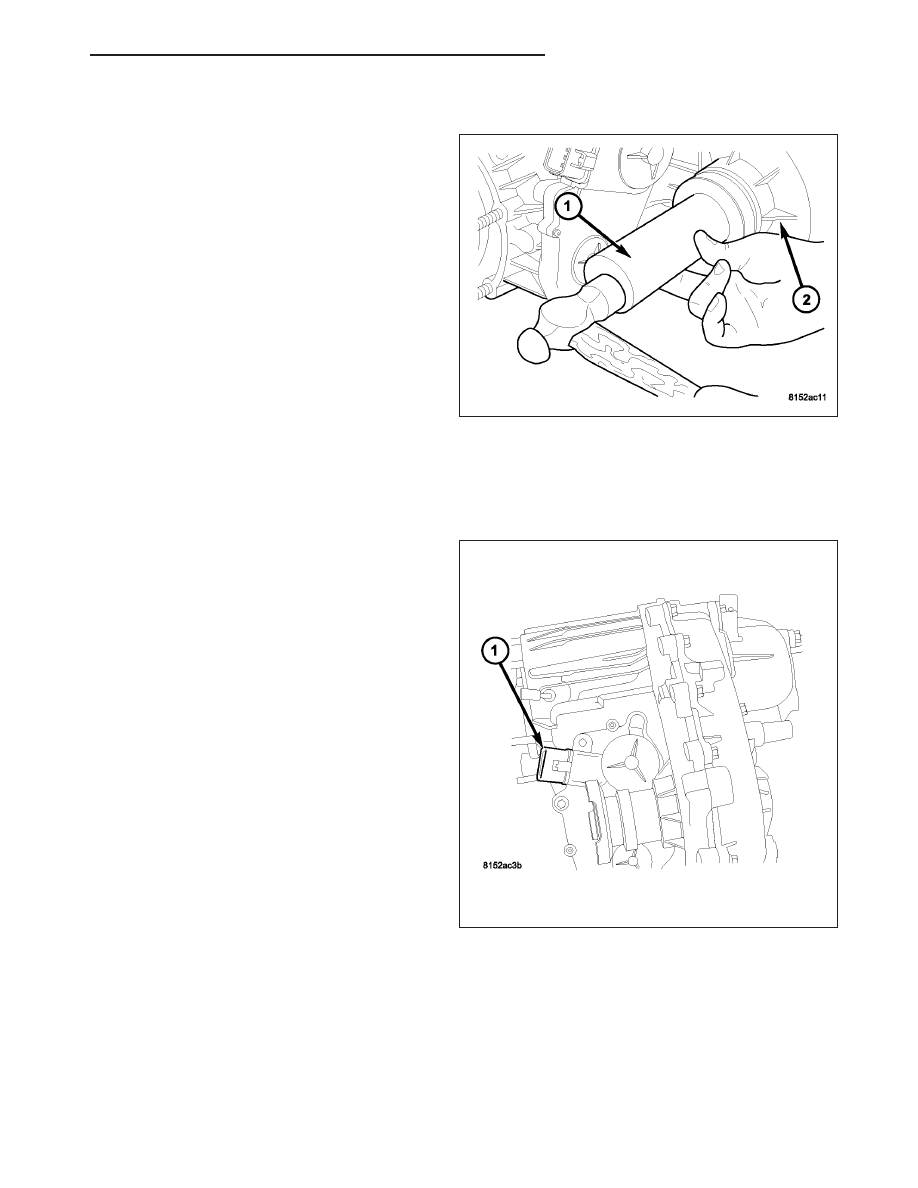
SENSOR-MODE
DESCRIPTION
The transfer case mode sensor (1) provides the Front
Control Module (FCM) feedback about the position of
the transfer case. The sensor consists of a linear ana-
log position sensor that converts the motor output
shaft position into a DC signal. The FCM must supply
5VDC (+/- 0.5v) to the sensor whenever the FCM is
not in sleep mode and monitor the shift motor position.
The sensor position is monitored when the ignition is
in the RUN position and for 10 seconds after the igni-
tion is shifted to the OFF position. The sensor is
mechanically linked to the shaft of the cam which
allows the transfer case to shift. The mode sensor will
draw less than 20 mA of current during operation.
OPERATION
During normal vehicle operation, the Front Control Module (FCM) monitors the mode sensor outputs at least every
2 milliseconds when the shift motor is stationary or active.
Refer to SECTOR ANGLES vs. TRANSFER CASE POSITION for the relative angles of the transfer case shift sector
versus the interpreted transfer case gear operating mode.
SECTOR ANGLES vs. TRANSFER CASE POSITION
ND
TRANSFER CASE - NV233
21 - 909

Shaft Angle (Degrees)
Transfer Case Position
+20
4LO
0
N
-20
2WD
-40
4HI
NOTE: All the parameter voltages referred to in the following information are calibrated items in the con-
troller software and are subject to change.
NOTE: For a further explanation of Phase 1 through 3 shifting, (Refer to 8 - ELECTRICAL/ELECTRONIC
CONTROL MODULES/TRANSFER CASE CONTROL MODULE - OPERATION).
The following information describes the different mode sensor positions:
•
4LO TARGET REGION - The position shall be considered 4LO if the voltage is greater than or equal to
encoder_4LO_min Volts and it is also less than or equal to encoder_4LO_max Volts.
•
4LO SHIFT LIMIT - During Phase 2 and Phase 3 shifting, shifts may become unidirectional when a voltage is
less than or equal to encoder_4LO_min Volts has been reached.
•
4HI TARGET REGION - The position shall be considered 4HI if the voltage is greater than or equal to
encoder_4HI_min Volts and it is also less than or equal to encoder_4HI_max Volts.
•
NEUTRAL TARGET REGION - The position shall be considered NEUTRAL if the voltage is greater than or
equal to encoder_Neutral_min Volts and it is also less than or equal to encoder_Neutral_max Volts.
•
2WD TARGET REGION - The position shall be considered 2WD if the voltage is greater than or equal to
encoder_2WD_min Volts and it is also less than or equal to encoder_2WD_max Volts.
•
2WD SHIFT LIMIT - During Phase 2 and Phase 3 shifting, shifts may become unidirectional when a voltage is
greater than or equal to encoder_2WD_min Volts has been reached.
The mode sensor position will be considered invalid by the FCM if the voltage is greater than or equal to encoder-
_High_Range_Limit Volts or if it is less than or equal to encoder_Low_Range_Limit Volts.
Refer to MODE SENSOR VOLTAGES - NV233 table for the mode sensor voltages.
MODE SENSOR VOLTAGES - NV233
Parameter Name
Voltage
encoder_4HI_Min
4.26
encoder_4HI_Max
4.36
encoder_2WD_Min
3.36
encoder_2WD_Max
3.44
encoder_Neutral_Min
2.45
encoder_Neutral_Max
2.54
encoder_4LO _Min
1.48
encoder_4LO _Max
1.57
encoder_High_Range_Limit
4.51
encoder_Low_Range _Limit
0.50
21 - 910
TRANSFER CASE - NV233
ND
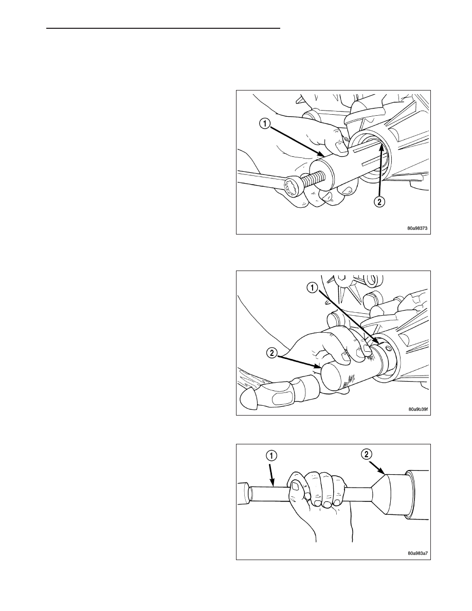
BUSHING/SEAL-REAR RETAINER
REMOVAL
1. Raise vehicle.
2. Remove rear propeller shaft. (Refer to 3 - DIFFER-
ENTIAL & DRIVELINE/PROPELLER SHAFT/PRO-
PELLER SHAFT - REMOVAL)
3. Using a suitable pry tool or slide-hammer mounted
screw, remove the rear retainer seal.
4. Using Remover 8158 (1), remove the bushing from
rear retainer.
INSTALLATION
1. Clean fluid residue from sealing surface and
inspect for defects.
2. Position replacement bushing in rear retainer with
fluid port in bushing aligned with slot in retainer.
3. Using Installer 8157 (2), drive bushing (1) into
retainer until installer seats against case.
4. Using Installer D-163 (2), install seal in rear
retainer.
5. Install the rear propeller shaft. (Refer to 3 - DIF-
FERENTIAL & DRIVELINE/PROPELLER SHAFT/
PROPELLER SHAFT - INSTALLATION)
6. Verify proper fluid level.
7. Lower vehicle.
ND
TRANSFER CASE - NV233
21 - 911
Нет комментариевНе стесняйтесь поделиться с нами вашим ценным мнением.
Текст