Dodge Dakota (ND). Manual — part 343
*LEFT FRONT LOCKS ONLY – ALL OTHERS INOPERATIVE (CONTINUED)
For the Power Door Lock circuit diagram (Refer to 8 - ELECTRICAL/POWER LOCKS - SCHEMATICS AND DIA-
GRAMS).
For a complete wiring diagram Refer to Section 8W.
Possible Causes
(P1) DOOR UNLOCK DRIVER LEFT FRONT CIRCUIT SHORTED TO GROUND
(P392) DOOR LOCK DRIVER RIGHT DOORS CIRCUIT SHORTED TO (G778) DOOR UNLOCK DRIVER
RIGHT DOORS
(P5) DOOR UNLOCK DRIVER LEFT REAR SHORTED TO (P393) DOOR LOCK DRIVER LEFT DOORS
INSTRUMENT CLUSTER
Diagnostic Test
1.
CHECK FOR ACTIVE DTC’s
Turn the ignition on.
With the scan tool, read active DTC’s.
Does the scan tool display any door lock related DTC’s?
No
>> Go To 2
Yes
>> Refer to symptom list for problems related to Power Door
Locks. Diagnose and repair the DTC’s
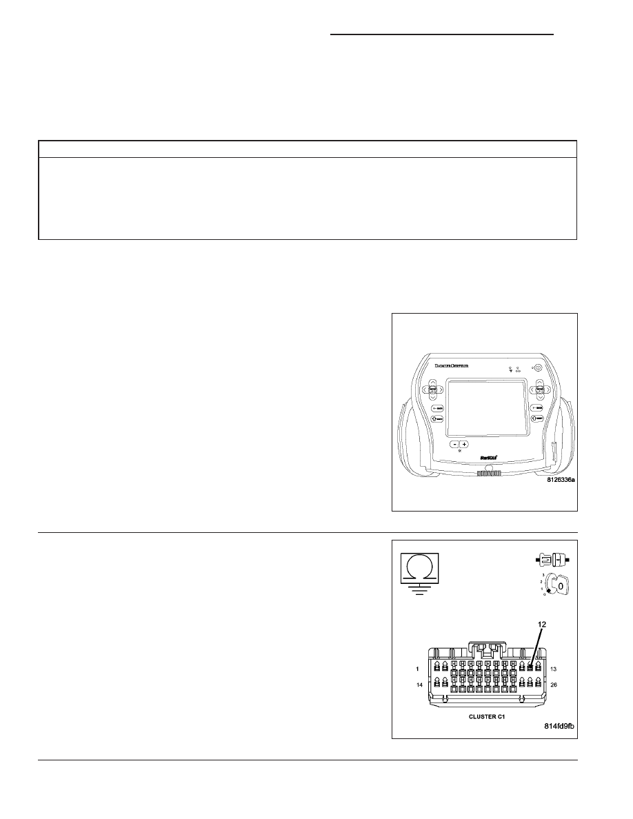
2.
CHECK (P1) DOOR UNLOCK DRIVER LEFT FRONT FOR
SHORT TO GROUND
Turn the ignition off.
Disconnect the Cluster C1 connector.
Measure the resistance between ground and the (P1) Door Unlock
Driver Left Front circuit.
Is the resistance below 1000.0 ohms?
No
>> Go To 3
Yes
>> Repair the (P1) Door Unlock Driver Left Front circuit for a
short to ground.
Perform BODY VERIFICATION TEST - VER 1. (Refer to 8
- ELECTRICAL/POWER LOCKS - DIAGNOSIS AND
TESTING)
8N - 48
POWER LOCKS - ELECTRICAL DIAGNOSTICS
ND

*LEFT FRONT LOCKS ONLY – ALL OTHERS INOPERATIVE (CONTINUED)
3.
CHECK THE (P5) DOOR UNLOCK DRIVER LEFT REAR FOR A SHORT TO THE (P393) DOOR LOCK
DRIVER LEFT DOORS
Measure the resistance between the (P5) Door Unlock Driver Left
Rear/Liftgate and the (P393) Door Lock Driver Left Doors circuits.
Is the resistance below 2.0 ohms?
No
>> Go To 4
Yes
>> Repair the (P5) Door Unlock Driver Left Rear circuit for a
short to the (P393) Door Lock Driver Left Doors circuit.
Perform BODY VERIFICATION TEST - VER 1. (Refer to 8
- ELECTRICAL/POWER LOCKS - DIAGNOSIS AND
TESTING)
4.
CHECK THE (P392) DOOR LOCK DRIVER RIGHT DOORS CIRCUIT FOR A SHORT TO THE (G778) DOOR
UNLOCK DRIVER RIGHT DOORS CIRCUIT
Measure the resistance between the (P392) Door Lock Driver Right
Doors circuit and the (G778) Door Unlock Driver Right Doors circuit.
Is the resistance below 2.0 ohms?
No
>> Replace the Instrument Cluster in accordance with service
information. Perform BODY VERIFICATION TEST - VER
1. (Refer to 8 - ELECTRICAL/POWER LOCKS - DIAGNO-
SIS AND TESTING)
Yes
>> Repair the (P392) Door Lock Driver Right Doors circuit for
a short to the (G778) Door Unlock Driver Right Doors cir-
cuit.
Perform BODY VERIFICATION TEST - VER 1. (Refer to 8
- ELECTRICAL/POWER LOCKS - DIAGNOSIS AND
TESTING)
ND
POWER LOCKS - ELECTRICAL DIAGNOSTICS
8N - 49

*RIGHT DOORS FAIL TO LOCK AND UNLOCK – QUAD CAB
8N - 50
POWER LOCKS - ELECTRICAL DIAGNOSTICS
ND
*RIGHT DOORS FAIL TO LOCK AND UNLOCK – QUAD CAB (CONTINUED)
For the Power Door Lock circuit diagram (Refer to 8 - ELECTRICAL/POWER LOCKS - SCHEMATICS AND DIA-
GRAMS)
For a complete wiring diagram Refer to Section 8W.
Possible Causes
DTC PRESENT
(P392) DOOR LOCK DRIVER RIGHT DOORS WIRE OPEN
(G778) DOOR UNLOCK DRIVER RIGHT DOORS WIRE OPEN
DOOR LATCH
INSTRUMENT CLUSTER
Diagnostic Test
1.
DTC PRESENT
Turn the ignition on.
With the scan tool, read DTC’s.
Does the scan tool display any Door Lock related DTC’s?
Yes
>> Refer to symptom list for problems related to Power Door
Locks and diagnose and repair DTC’s.
No
>> Go To 2
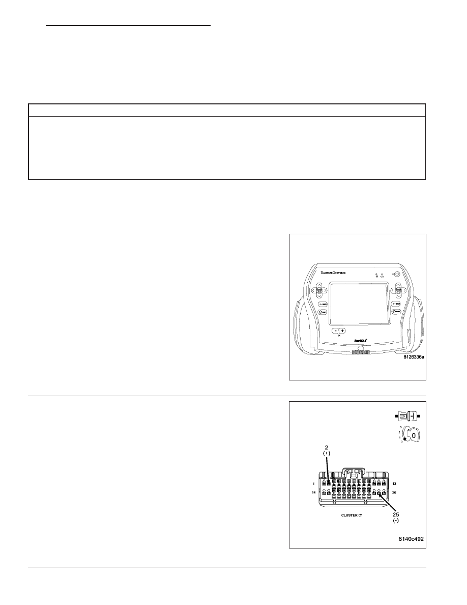
2.
INSTRUMENT CLUSTER
Turn the ignition off.
Disconnect the Instrument Cluster C1 connector.
Connect a jumper wire between the (G778) Door Unlock Driver Right
Doors circuit in the Instrument Cluster C1 connector and ground.
Momentarily connect a fused jumper wire between the Fused B+ cir-
cuit and the (P392) Door Lock Driver Right Doors circuit in the Instru-
ment Cluster C1 connector.
Reverse the jumper wires to drive the motors in the opposite direction.
Did the Right Doors lock and unlock?
Yes
>> Replace the Instrument Cluster.
Perform BODY VERIFICATION TEST - VER 1. (Refer to
BODY VERIFICATION TEST - VER 1.)
No
>> Go To 3
ND
POWER LOCKS - ELECTRICAL DIAGNOSTICS
8N - 51
Нет комментариевНе стесняйтесь поделиться с нами вашим ценным мнением.
Текст