Dodge Dakota (ND). Manual — part 273
U0141–LOST COMMUNICATION WITH FRONT CONTROL MODULE
For a complete wiring diagram Refer to Section 8W.
(Refer to 8 - ELECTRICAL/ELECTRONIC CONTROL MODULES - DIAGNOSIS AND TESTING) for the diagnostic
test procedure.
U0151-LOST COMMUNICATION WITH OCCUPANT RESTRAINT CONTROLLER
For a complete wiring diagram Refer to Section 8W.
(Refer to 8 - ELECTRICAL/ELECTRONIC CONTROL MODULES - DIAGNOSIS AND TESTING) for the diagnostic
test procedure.
U0156-LOST COMMUNICATION WITH EOM
For a complete wiring diagram Refer to Section 8W.
(Refer to 8 - ELECTRICAL/ELECTRONIC CONTROL MODULES - DIAGNOSIS AND TESTING) for the diagnostic
test procedure.
U0168-LOST COMMUNICATION WITH VEHICLE SECURITY CONTROL MODULE
(SKREEM/WCM)
For a complete wiring diagram Refer to Section 8W.
(Refer to 8 - ELECTRICAL/ELECTRONIC CONTROL MODULES - DIAGNOSIS AND TESTING) for the diagnostic
test procedure.
U0184-LOST COMMUNICATION WITH RADIO
For a complete wiring diagram Refer to Section 8W.
(Refer to 8 - ELECTRICAL/ELECTRONIC CONTROL MODULES - DIAGNOSIS AND TESTING) for the diagnostic
test procedure.
U0199-LOST COMMUNICATION WITH DRIVER DOOR MODULE
For a complete wiring diagram Refer to Section 8W.
(Refer to 8 - ELECTRICAL/ELECTRONIC CONTROL MODULES - DIAGNOSIS AND TESTING) for the diagnostic
test procedure.
U0208-LOST COMMUNICATION WITH HEATED SEAT CONTROL MODULE
For a complete wiring diagram Refer to Section 8W.
(Refer to 8 - ELECTRICAL/ELECTRONIC CONTROL MODULES - DIAGNOSIS AND TESTING) for the diagnostic
test procedure.
8J - 34
INSTRUMENT CLUSTER - ELECTRICAL DIAGNOSTICS
ND
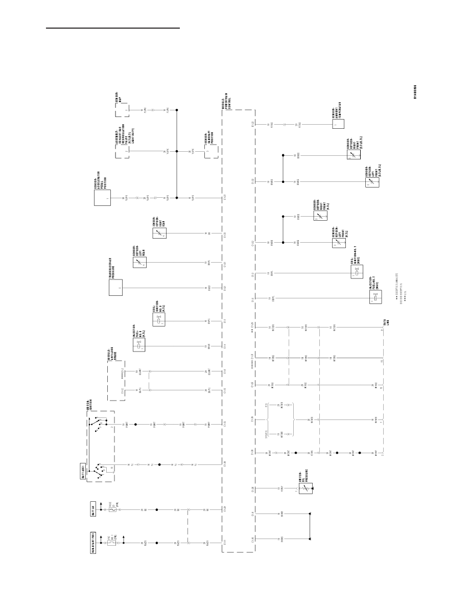
SCHEMATICS AND DIAGRAMS
CLUSTER
SYSTEM
SCHEMA
TIC
ND
INSTRUMENT CLUSTER - ELECTRICAL DIAGNOSTICS
8J - 35
CLUSTER
TABLE OF CONTENTS
page
page
CLUSTER
. . . . . . . . . . . . . . . . . . . . . . . . . 37
. . . . . . . . . . . . . . . . . . . . . . . . . . . 41
. . . . . . . . . . . . . . . . 44
. . . . . . . . . . . . . . . . . . . . . . . . . . . . . 45
. . . . . . . . . . . . . . . . . . . . . . . . . 46
. . . . . . . . . . . . . . . . . . . . . . . . . . . . 47
. . . . . . . . . . . . . . . . . . . . . . . . . 48
ABS INDICATOR
. . . . . . . . . . . . . . . . . . . . . . . . . 49
. . . . . . . . . . . . . . . . . . . . . . . . . . . 50
AIRBAG INDICATOR
. . . . . . . . . . . . . . . . . . . . . . . . . 50
. . . . . . . . . . . . . . . . . . . . . . . . . . . 51
BRAKE/PARK BRAKE INDICATOR
. . . . . . . . . . . . . . . . . . . . . . . . . 51
. . . . . . . . . . . . . . . . . . . . . . . . . . . 52
. . . . . . . . . . . . . . . . . . . . 52
CARGO LAMP INDICATOR
. . . . . . . . . . . . . . . . . . . . . . . . . 53
. . . . . . . . . . . . . . . . . . . . . . . . . . . 53
CHARGING INDICATOR
. . . . . . . . . . . . . . . . . . . . . . . . . 54
. . . . . . . . . . . . . . . . . . . . . . . . . . . 54
CRUISE INDICATOR
. . . . . . . . . . . . . . . . . . . . . . . . . 55
. . . . . . . . . . . . . . . . . . . . . . . . . . . 55
DOOR AJAR INDICATOR
. . . . . . . . . . . . . . . . . . . . . . . . . 55
. . . . . . . . . . . . . . . . . . . . . . . . . . . 56
ENGINE TEMPERATURE GAUGE
. . . . . . . . . . . . . . . . . . . . . . . . . 56
. . . . . . . . . . . . . . . . . . . . . . . . . . . 56
ENGINE TEMPERATURE INDICATOR
. . . . . . . . . . . . . . . . . . . . . . . . . 57
. . . . . . . . . . . . . . . . . . . . . . . . . . . 58
ETC INDICATOR
. . . . . . . . . . . . . . . . . . . . . . . . . 58
. . . . . . . . . . . . . . . . . . . . . . . . . . . 58
FOG LAMP INDICATOR
. . . . . . . . . . . . . . . . . . . . . . . . . 59
. . . . . . . . . . . . . . . . . . . . . . . . . . . 59
FUEL GAUGE
. . . . . . . . . . . . . . . . . . . . . . . . . 60
. . . . . . . . . . . . . . . . . . . . . . . . . . . 60
GEAR SELECTOR INDICATOR
. . . . . . . . . . . . . . . . . . . . . . . . . 61
. . . . . . . . . . . . . . . . . . . . . . . . . . . 62
HIGH BEAM INDICATOR
. . . . . . . . . . . . . . . . . . . . . . . . . 62
. . . . . . . . . . . . . . . . . . . . . . . . . . . 62
LOW FUEL INDICATOR
. . . . . . . . . . . . . . . . . . . . . . . . . 63
. . . . . . . . . . . . . . . . . . . . . . . . . . . 63
LOW OIL PRESSURE INDICATOR
. . . . . . . . . . . . . . . . . . . . . . . . . 64
. . . . . . . . . . . . . . . . . . . . . . . . . . . 64
MALFUNCTION INDICATOR LAMP (MIL)
. . . . . . . . . . . . . . . . . . . . . . . . . 65
. . . . . . . . . . . . . . . . . . . . . . . . . . . 65
ODOMETER
. . . . . . . . . . . . . . . . . . . . . . . . . 66
. . . . . . . . . . . . . . . . . . . . . . . . . . . 66
SEATBELT INDICATOR
. . . . . . . . . . . . . . . . . . . . . . . . . 67
. . . . . . . . . . . . . . . . . . . . . . . . . . . 68
PROGRAMMING . . . . . . . . . . . . . . . . . . . . . . 69
SECURITY INDICATOR
. . . . . . . . . . . . . . . . . . . . . . . . . 69
. . . . . . . . . . . . . . . . . . . . . . . . . . . 69
SERVICE 4WD INDICATOR
. . . . . . . . . . . . . . . . . . . . . . . . . 70
. . . . . . . . . . . . . . . . . . . . . . . . . . . 70
SHIFT INDICATOR (TRANSFER CASE)
. . . . . . . . . . . . . . . . . 71
. . . . . . . . . . . . . . . . . 71
. . . . . . . . . . . . . . . . . 72
. . . . . . . . . . . . . . . . . 72
SPEEDOMETER
. . . . . . . . . . . . . . . . . . . . . . . . . 73
. . . . . . . . . . . . . . . . . . . . . . . . . . . 73
TACHOMETER
. . . . . . . . . . . . . . . . . . . . . . . . . 74
. . . . . . . . . . . . . . . . . . . . . . . . . . . 74
TOW/HAUL INDICATOR
. . . . . . . . . . . . . . . . . . . . . . . . . 75
. . . . . . . . . . . . . . . . . . . . . . . . . . . 75
TRACTION CONTROL INDICATOR
. . . . . . . . . . . . . . . . . . . . . . . . . 75
. . . . . . . . . . . . . . . . . . . . . . . . . . . 76
TRANS TEMP INDICATOR
. . . . . . . . . . . . . . . . . . . . . . . . . 76
. . . . . . . . . . . . . . . . . . . . . . . . . . . 77
TURN SIGNAL INDICATOR
. . . . . . . . . . . . . . . . . . . . . . . . . 77
. . . . . . . . . . . . . . . . . . . . . . . . . . . 77
WASHER FLUID INDICATOR
. . . . . . . . . . . . . . . . . . . . . . . . . 78
. . . . . . . . . . . . . . . . . . . . . . . . . . . 79
8J - 36
CLUSTER
ND
CLUSTER
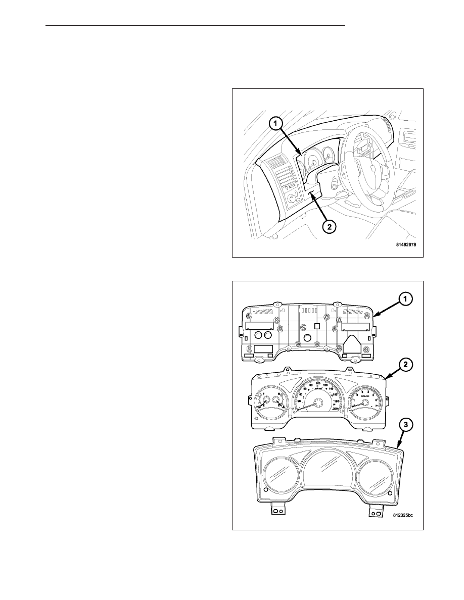
DESCRIPTION
The instrument cluster (1) for this model is an Electro-
Mechanical Instrument Cluster (EMIC) that is located
in the instrument panel above the steering column
opening, directly in front of the driver. The remainder
of the EMIC, including the mounts and the electrical
connections, are concealed within the instrument
panel behind the cluster bezel (2). Besides analog
gauges and indicators, the EMIC module incorporates
a single blue-green digital Vacuum Fluorescent Dis-
play (VFD) unit for displaying odometer/trip odometer
information, engine hours, automatic transmission
gear selector position (PRNDL), several warning or
reminder indications and certain diagnostic informa-
tion. The instrument cluster for this model also
includes the hardware and software necessary to
serve as the electronic body control module and is
sometimes referred to as the Cab Compartment Node
or CCN.
The EMIC gauges and indicators are visible through a
dedicated opening in the cluster bezel on the instru-
ment panel and are protected by a clear plastic cluster
lens that is integral to a cluster lens, hood and mask
unit (3). Just behind the cluster lens is the cluster
hood and an integral cluster mask, which are con-
structed of molded black plastic. Two different masks
are used, one with black rings and one with silver
rings around the gauge openings. The cluster hood
serves as a visor and shields the face of the cluster
from ambient light and reflections to reduce glare,
while the cluster mask serves to separate and define
the individual gauges and indicators of the EMIC. A
black plastic odometer/trip odometer switch button
protrudes through dedicated holes in the cluster mask
and the cluster lens, located near the lower edge of
the cluster just to the left of the fuel gauge. The
molded plastic EMIC lens, hood and mask unit has
four integral mounting tabs, two each on the upper
and lower edges of the unit. These mounting tabs are
used to secure the EMIC to the molded plastic instru-
ment panel cluster carrier with four screws.
The rear of the cluster housing and the EMIC elec-
tronic circuitry are protected by a molded plastic rear
cover (1), which is secured to the cluster housing with
fourteen screws, while eight screws installed around
the outside perimeter of the rear cover secure it to the
cluster lens, hood and mask unit. The rear cover
includes clearance holes for the cluster connector receptacles. The connector receptacles on the back of the cluster
electronic circuit board connect the EMIC to the vehicle electrical system through three take outs with connectors
from the instrument panel wire harness.
ND
CLUSTER
8J - 37
Нет комментариевНе стесняйтесь поделиться с нами вашим ценным мнением.
Текст