Chrysler Le Baron, Dodge Dynasty, Plymouth Acclaim. Manual — part 199
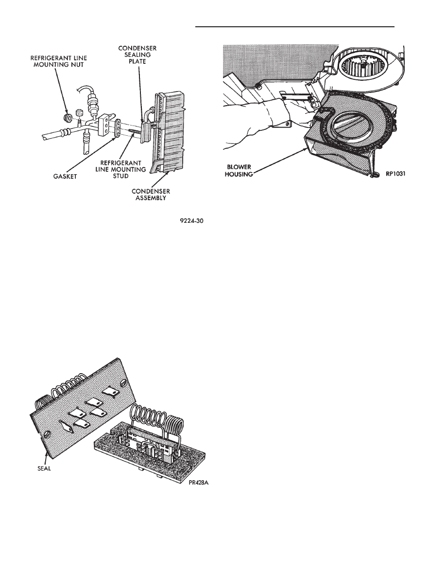
new condenser, refer to Oil Level in the Refrigerant
section. Tighten the refrigerant line mounting nut to
23 N
Im (200 inch pounds).
Evacuate and recharge system.
BLOWER MOTOR
BLOWER MOTOR VIBRATION AND/OR NOISE
DIAGNOSIS
The resistor block (Fig. 3), supplies the blower mo-
tor with varied voltage (low and middle speeds) or
battery voltage (high speed).
CAUTION: Stay clear of the blower motor and resis-
tor block (Hot). Do not operate the blower motor
with the resistor block removed from the heater-A/C
housing.
Refer to the Blower Motor Vibration/Noise chart in
this section for diagnosis.
BLOWER MOTOR ELECTRICAL DIAGNOSIS
Refer to the Blower Motor Electrical System Diag-
nosis chart in this section. Also refer to Group 8W,
Wiring Diagrams for more information.
REMOVAL AND INSTALLATION
(1) Disconnect the negative battery cable.
(2) Remove the glove box. Refer to Group 8E, In-
strument Panel.
(3) On vehicles equipped with A/C, disconnect the
two vacuum
lines from the recirculating air door actuator. Dis-
connect blower lead wire connector.
(4) Remove two screws at the top of the blower
housing, securing it to the unit cover.
(5) Remove five screws from around the blower
housing and separate the blower housing from the
unit (Fig. 4).
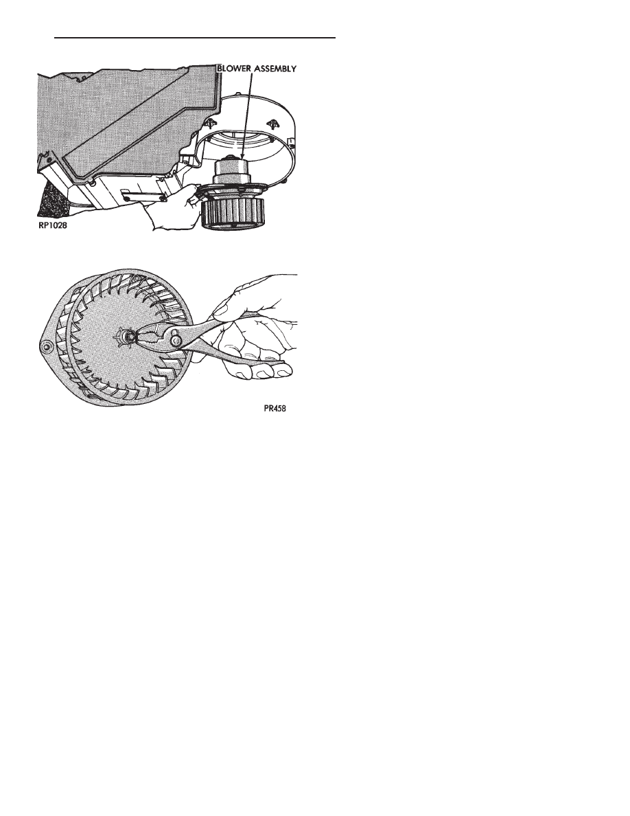
(6) Remove three screws securing the blower and
wheel assembly to the heater or A/C unit housing.
Then separate the assembly from the unit (Fig. 5).
To install, reverse the preceding operation.
BLOWER MOTOR WHEEL ASSEMBLY
REMOVAL AND INSTALLATION
Blower motor must be removed from vehicle before
performing this operation. Refer to Blower Motor Re-
moval and Installation.
(1) Remove the spring type retaining ring from the
center of the blower wheel (Fig. 6). Note the location
of the blower wheel on the blower motor shaft.
(2) Remove blower wheel from blower motor shaft.
To install, reverse the preceding operation. To pre-
vent noise or vibration, rotate the blower wheel by
hand to check for rubbing.
Fig. 2 A/C Condenser Refrigerant Lines—Typical
Fig. 3 Blower Motor Resistor Block—Typical
Fig. 4 Blower Housing—Typical
24 - 58
HEATING AND AIR CONDITIONING
Ä

BLOWER MOTOR NOISE/VIBRATION DIAGNOSIS
Ä
HEATING AND AIR CONDITIONING
24 - 59

BLOWER MOTOR ELECTRICAL SYSTEM DIAGNOSIS
24 - 60
HEATING AND AIR CONDITIONING
Ä
HEATER-A/C UNIT ASSEMBLY—REMOVAL AND
INSTALLATION
AP, AC, AY BODY PROCEDURE
WARNING: IF EQUIPPED WITH A/C, THE REFRIG-
ERATION SYSTEM MUST BE COMPLETELY EMPTY
BEFORE PROCEEDING WITH THIS OPERATION.
(1) Disconnect battery NEGATIVE cable.
(2) Drain radiator and disconnect heater hoses at
unit. Tape heater tubes to keep from leaking during
removal. Refer to Group 7, Cooling System.
(3) Remove A/C condensate drain and disconnect
vacuum lines.
(4) Inside passenger compartment, perform as fol-
lows, according to body designation.
(a) AC-body, remove right upper and lower un-
der-panel silencers.
(b) AP & AC-bodies, remove steering column
cover.
(c) AC-body, remove left under-panel silencer.
(5) Position front seat or right front seat full rear.
(a) AP-body, remove right A-pillar trim.
(b) Remove right cowl side trim.
(6) Remove glove box.
(a) AC-body, remove right instrument panel re-
inforcement.
(7) AP-body only:
(a) Remove right instrument panel lower mount-
ing screw.
(b) Remove center bezel.
(c) Remove lower center module cover.
(d) Remove floor console.
(e) Remove instrument panel support brace (from
steering column opening to right cowl side at bot-
tom of instrument panel).
(f) Remove instrument panel to support bracket
(below glove box opening).
(g) Remove ash receiver.
(h) Remove radio.
(i) Remove panel top cover.
(j) Remove three right side panel to fence (below
windshield) attaching screws.
(8) AC-body, remove ash receiver.
(9) AP body, pull right lower side of instrument
panel rearward.
(10) Remove
center
distribution
and
defroster
adapter ducts.
(11) AP and AC-bodies, disconnect relay module.
(12) AP-body, remove instrument panel to unit
bracket.
(13) AP-body, remove lower air distribution duct.
(14) Disconnect blower motor wire connector.
(15) Disconnect demister hoses from top of unit.
(16) For Non-ATC equipped vehicles, disconnect
the temperature control cable flag from the bottom of
the heater-A/C unit. Then un-clip the cable from the
left side of the heat distribution duct. Swing the ca-
ble out of the way to the left. Disconnect the vacuum
lines at the unit.
(17) For ATC equipped vehicles, disconnect the in-
strument panel wiring from the rear face of the ATC
control unit.
(18) AC body, disconnect right 25-way connector
bracket and fuse block from panel.
(19) Fold floor right side carpet back (except AC
body).
(20) From engine compartment, remove four unit
attaching nuts.
(21) Remove unit hanger strap lower screw, and
rotate strap.
(22) Move
heater-A/C
unit
rearward
to
clear
mounting studs, and lower unit.
(23) AP-body, remove demister adapter from top of
unit.
(24) While pulling the lower right of instrument
panel rearward:
(a) Slide unit upright from under instrument
panel for AP-body.
(b) Except for AP-body, rotate unit while pulling
from under instrument panel.
To install, reverse the preceding operation.
Fig. 5 Blower Motor and Wheel Assembly
Fig. 6 Blower Wheel Retaining Ring Removal and
Installation
Ä
HEATING AND AIR CONDITIONING
24 - 61
Нет комментариевНе стесняйтесь поделиться с нами вашим ценным мнением.
Текст