Chrysler Le Baron, Dodge Dynasty, Plymouth Acclaim. Manual — part 197
(5) Carefully pull the resistor block straight out
from the cowl plenum opening and remove the resis-
tor block from the vehicle.
To install, reverse the preceding operation. The
coils on the Resistor Block should not be contacting
one another. Before installation, gently separate the
coils (with fingers only) if one coil is contacting an-
other.
AA, AP, AY, AND AC BODY
(1) Raise the hood and remove the windshield
wiper arm assemblies.
(2) Remove
five
cowl-plenum
grille
attaching
screws and carefully lift the grille from the vehicle.
(3) (AA and AP): Locate and remove four air in-
take shield attaching screws and lift the shield from
the vehicle.
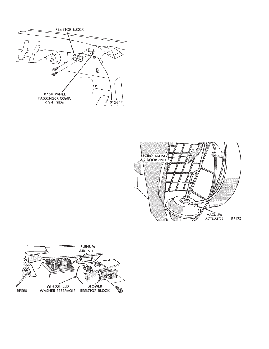
(4) (AC and AY): Remove two resistor block termi-
nal cover screws and remove cover.
(5) Disconnect the wire connector from the resistor
block located behind the windshield washer reservoir
(Fig. 7).
(6) Remove two blower resistor block attaching
screws. Then carefully pull the resistor block forward
until the coils clear the plenum and lift it from the
vehicle.
To install, reverse the preceding operation. The
coils on the Resistor Block should not be contacting
one another. Before installation, gently separate the
coils (with fingers only) if one coil is contacting an-
other.
VACUUM ACTUATOR—FRESH/RECIRC DOOR
This actuator is located on the passenger side of
the heater-A/C housing.
REMOVAL AND INSTALLATION
(1) AA, AC or AY Body: Remove silencer cover un-
der the instrument panel (below glove box).
(2) Remove glove box assembly. Refer to Group 8E,
Instrument Panel.
(3) Disconnect vacuum lines.
(4) Locate and remove the two vacuum actuator at-
taching screws.
(5) Disengage the actuator arm linkage from the
door pivot and remove the vacuum actuator (Fig. 8)
from vehicle.
To install, reverse the preceding operation.
AIR DISTRIBUTION DUCT
REMOVAL AND INSTALLATION
AA BODY
On AA Body the instrument panel must be rolled
down to service duct. Refer to Group 8E, Instrument
Panel.
AC, AP, AY BODY
(1) Remove lower instrument panel module. Refer
to Group 8E, Instrument Panel.
(2) Remove distribution duct attaching screws from
under the front edge of the instrument panel (Fig. 9).
(3) Slide duct downward and remove from vehicle.
To install, reverse the preceding operation.
Fig. 6 Blower Resistor Block Location—AJ and AG
Body
Fig. 7 Blower Resistor Block Location—AA, AP, AY
and AC Body
Fig. 8 Recirculating Air Door Vacuum
Actuator—Typical
24 - 50
HEATING AND AIR CONDITIONING
Ä
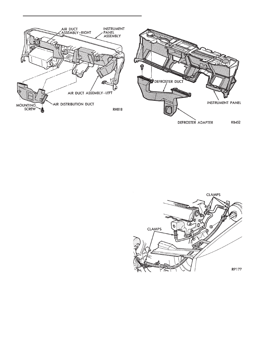
DEFROSTER DUCT ADAPTER
REMOVAL AND INSTALLATION
AA BODY
On AA body, the instrument panel must be rolled
down to service duct. Refer to Group 8E, Instrument
Panel.
AC, AP, AY BODY
(1) Remove air distribution duct.
(2) Separate the defroster adapter from the heater-
A/C unit and pull the adapter downward and out
from under the instrument panel.
To install, reverse the preceding operation.
DEFROSTER DUCT
REMOVAL AND INSTALLATION
AA, AG, AND AJ BODY
On AA, AG, and AJ Body, the instrument panel
must be rolled down to service duct. Refer to Group
8E, Instrument Panel.
AC, AP, AY BODY
(1) Remove the air distribution duct.
(2) Remove the defroster duct adapter.
(3) Remove the instrument panel top cover. Refer
to Group 8E, Instrument Panel.
(4) Locate and remove defroster duct attaching
screws at the ends of each outlet (Fig. 10).
(5) Allow the defroster duct to drop downward and
remove it from the vehicle.
To install, reverse the preceding operation.
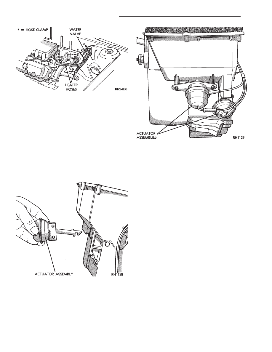
HEATER HOSES
REMOVAL AND INSTALLATION
Review Cooling System Precautions before
proceeding with this operation.
(1) Drain engine cooling system. Refer to Group 7,
Cooling System.
(2) Loosen clamps at each end of hose to be re-
moved (Figs. 11 or 12).
(3) Carefully rotate hose back and forth while tug-
ging slightly away from connector nipple.
CAUTION: When removing hoses from heater core
inlet or outlet nipples DO NOT exert excess pres-
sure. The heater core may become damaged and
leak engine coolant into heater-A/C unit.
Fig. 9 Air Distribution Ducts—Typical
Fig. 10 Removing or Installing Defroster
Duct—Typical
Fig. 11 Heater Hose Routing—2.2 L, 2.5 L
Engines—Typical
Ä
HEATING AND AIR CONDITIONING
24 - 51
To install, reverse the preceding operation.
VACUUM ACTUATORS—MODE DOORS
The Vacuum Actuators for the Mode Doors are lo-
cated on the drivers side of heater/AC housing above
the accelerator pedal.
REMOVAL
(1) Remove the instrument panel cover under the
steering column. Refer to Group 8E, Instrument
Panel.
Heat/Defrost Actuator:
Remove two screws from bracket. Lift actuator up-
ward and pull out (Fig. 13).
Mode Door Actuator:
Remove two screws from bracket (Fig. 14). Rotate
actuator counter-clockwise to unhook from door and
pull to remove.
INSTALLATION
Heat/Defrost Actuator:
Install actuator link through housing and insert in
heat defrost door slot. Push down to hook link to
door. Locate the bracket to the housing and install
two screws.
Mode Door Actuator:
Insert the actuator shaft through the hole in the
housing
and
heat/defrost
door.
Attach
through
mounting hole in the mode door. Install two screws
in bracket.
Install the instrument panel cover under the steer-
ing column.
AIR DISTRIBUTION DUCT
REMOVAL AND INSTALLATION
(1) Instrument panel assembly must be removed.
Refer to Group 8E, Instrument Panel.
(2) After instrument panel has been removed, sep-
arate the defroster/demister ducts from the air distri-
bution duct.
(3) Remove the air distribution duct-to-instrument
panel mounting screws (Fig. 15).
To install, reverse removal procedure.
DEFROSTER DUCTS/DEMISTER DUCTS AND
HOSES
REMOVAL AND INSTALLATION
(1) Instrument panel assembly must be removed.
Refer to Group 8E, Instrument Panel.
(2) After instrument panel has been removed, sep-
arate the defroster/demister ducts from the air distri-
bution duct.
(3) Remove the demister tubes and hoses (Fig. 16).
To install, reverse removal procedure.
Fig. 12 Heater Hose Routing—3.0 L Engine—Typical
Fig. 13 Removing or Installing Heat/Defrost Vacuum
Actuator Assembly
Fig. 14 Mode Door Vacuum Actuators
24 - 52
HEATING AND AIR CONDITIONING
Ä
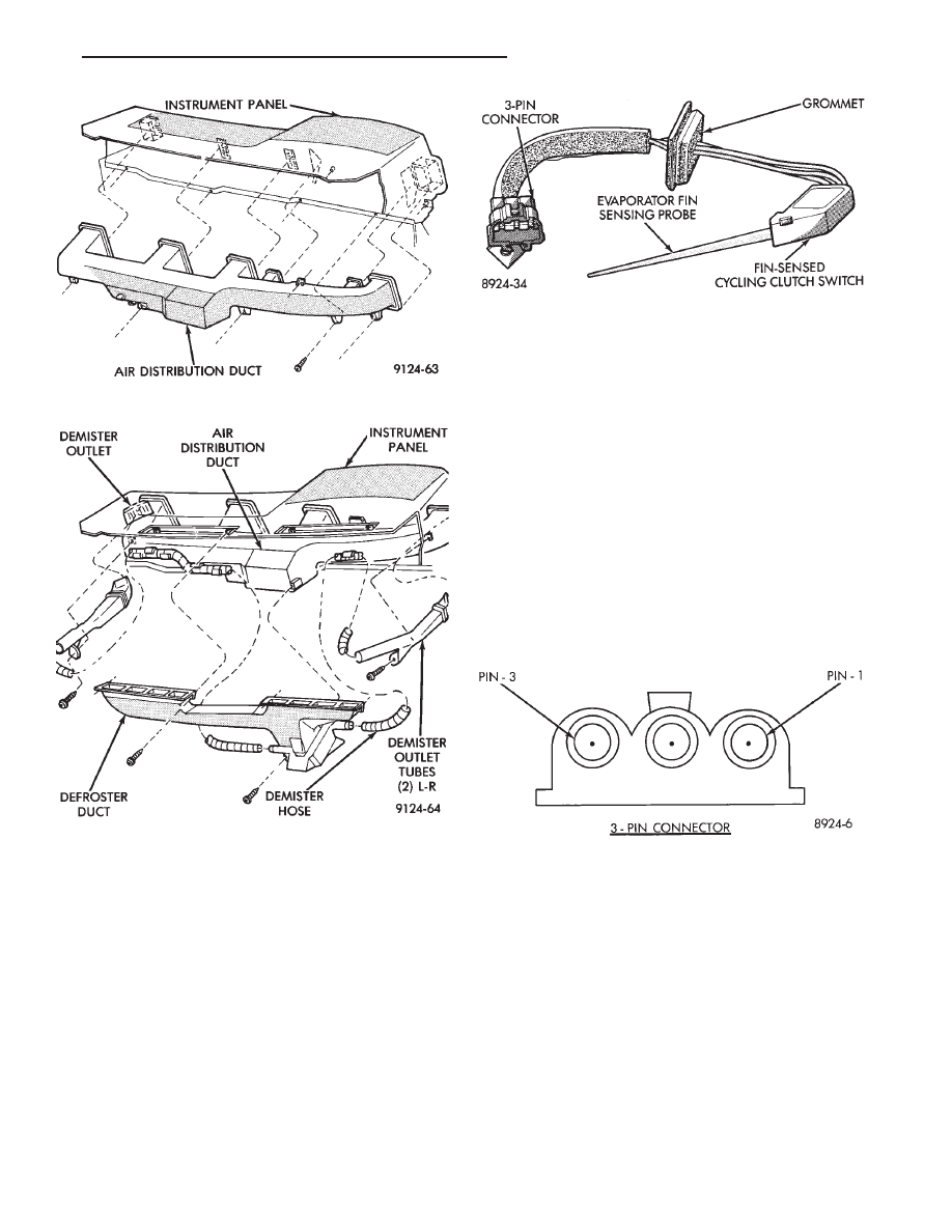
FIN-SENSING CYCLING CLUTCH SWITCH
The Fin-Sensing Cycling Clutch Switch (FCCS)
(Fig. 17) is located in the heater-A/C unit housing
near the blower motor and placed in the evaporator
fins. The FCCS prevents evaporator condensate
freeze-up. This is done by cycling the compressor
clutch OFF when evaporator temperature drops be-
low freeze point. It cycles ON when the evaporator
temperature rises above freeze point. The FCCS uses
a thermistor probe in a capillary tube inserted be-
tween the evaporator fins in the heater-A/C unit
housing. If the compressor clutch does not cycle, and
all other clutch circuit components test correct, test
the switch.
At temperatures above 32°C (90°F) the compressor
clutch may engage continuously and not cycle. This
is due to evaporator temperature above the freezing
point.
DIAGNOSIS
The work area and vehicle must be between 21°C
(70°F) and 32°C (90°F) when testing the Fin-sensing
Cycling Switch.
(1) Disconnect the 3-wire connector from switch
lead located behind the glove box.
(2) Test for voltage between pin #1 to pin #3 on
the wire harness connector (Fig. 18). If voltage is not
detected, refer to the Front Wheel Drive Car-Wiring
Diagrams Service Manual. If voltage is detected,
jump pin #1 to pin #3 using a jumper wire. Com-
pressor clutch should engage.
(3) If compressor clutch engages, test for continuity
from terminal pin #1 to pin #3 of the switch lead
connector. Continuity should be detected. If not, re-
place the Fin-sensing Cycling Clutch Switch.
REMOVAL AND INSTALLATION
(1) Remove the cover/housing from the heater-A/C
blower motor. Refer to Blower Motor removal and in-
stallation. Remove the cover only. Blower motor or
blower motor wheel removal is not necessary.
(2) Disconnect the (three pin) wiring pigtail con-
nector from the clutch switch sensor harness (located
on the outside of the A/C-heater housing). Push the
wire harness grommet (attached to the A/C-heater
Fig. 15 Air Distribution Duct
Fig. 16 Defroster Ducts/Demister Ducts and Hoses
Fig. 17 Fin-sensing Cycling Clutch Switch
Fig. 18 Fin-sensing Cycling Clutch Switch Harness
Connector
Ä
HEATING AND AIR CONDITIONING
24 - 53
Нет комментариевНе стесняйтесь поделиться с нами вашим ценным мнением.
Текст