Chrysler Le Baron, Dodge Dynasty, Plymouth Acclaim. Manual — part 198
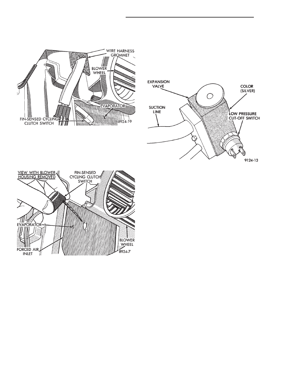
housing) through the hole in the housing. Feed the
wire harness and connector through the opening and
into the housing (Fig. 19).
(3) Work through the air inlet opening (to the left of
the blower motor wheel). Pull the fin-sensing cycling
switch from the A/C evaporator (Fig. 20). The metal
probe on the switch is pushed into the evapora-
tor approximately three inches.
To install, reverse the preceding operation. The
switch probe should not be installed in the original
location (hole). Insert the probe in the evaporator coil
approximately 5 mm (3 to 4 fins) to the right or left of
the position it was removed. This will insure correct
temperature sensing and system performance. Exces-
sive force should not be required for probe insertion.
Care should be taken not to damage the A/C evaporator
coil or the switch probe.
LOW OR DIFFERENTIAL PRESSURE CUT-OFF
SWITCH
The Low Pressure Cut-Off (LPCO) Switch (Fig. 21)
monitors the refrigerant gas pressure on the suction
side of the system. The LPCO is located on the ex-
pansion valve, and the expansion valve is silver in
color when a fixed displacement compressor is used.
The LPCO turns off voltage to the compressor clutch
coil when refrigerant gas pressure drops to levels
that could damage the compressor. The LPCO is a
sealed factory calibrated unit. It must be replaced if
defective.
LPCO SWITCH DIAGNOSIS
The work area must not be below 10°C (50°F) to
test the compressor clutch circuit.
(1) With gear selector in park or neutral and park
brake set, start engine and allow to idle.
(2) Raise hood and disconnect LPCO switch con-
nector boot.
(3) Using a suitable jumper wire, jump across the
terminals inside wire connector boot.
(4) If the compressor clutch does not engage, the
cycling clutch switch, wiring, relay, or fuse can be
defective. Refer to Group 8W, Wiring Diagrams.
(5) If clutch engages, connect manifold gauge set.
Read low pressure gauge. At pressure above 97 kPa
(14 psi) and above, LPCO switch will complete the
clutch circuit. If the low pressure gauge reads below
172 kPa (25 psi), the system is low on refrigerant
charge or empty due to a leak. Refer to Testing For
Refrigerant Leaks in the Refrigerant Service Proce-
dures section.
(6) Install connector boot on switch and repeat step
number 3. If the clutch does not engage, replace the
LPCO switch.
REMOVAL AND INSTALLATION
WARNING: THE REFRIGERATION SYSTEM MUST
BE COMPLETELY EMPTY BEFORE PROCEEDING
WITH THIS OPERATION. REFER TO REFRIGERANT
RECOVERY SECTION.
Fig. 21 Low Pressure Cut-Off Switch
Fig. 19 Remove or Install Wire Harness Grommet
Fig. 20 Remove or Install Fin-sensing Cycling
Clutch Switch
24 - 54
HEATING AND AIR CONDITIONING
Ä
(1) Disconnect the boot like wire connector at the
cut-off switch.
(2) Using a sender unit type socket, remove the
switch from the expansion valve (Fig. 22 or 23).
To install, assure an adequate seal by using a small
amount of thread sealing tape on the replacement
switch and reverse the preceding steps.
Evacuate and charge the system.
EXPANSION VALVE
DIAGNOSIS
BLACK EXPANSION VALVE TEST
Liquid CO
2
is required to test the expansion
valve. It is available from most welding supply
facilities. CO
2
is also available from companies
which service and sell fire extinguishers.
Review Safety Precautions and Warnings before pro-
ceeding with this operation. The work area must
be 21°C to 27°C (70°F to 85°F) when testing expansion
valve. To test the expansion valve:
(1) Connect a charging station or manifold gauge set
to the refrigerant system service ports.
(2) Verify the refrigerant charge level using the sight
glass method.
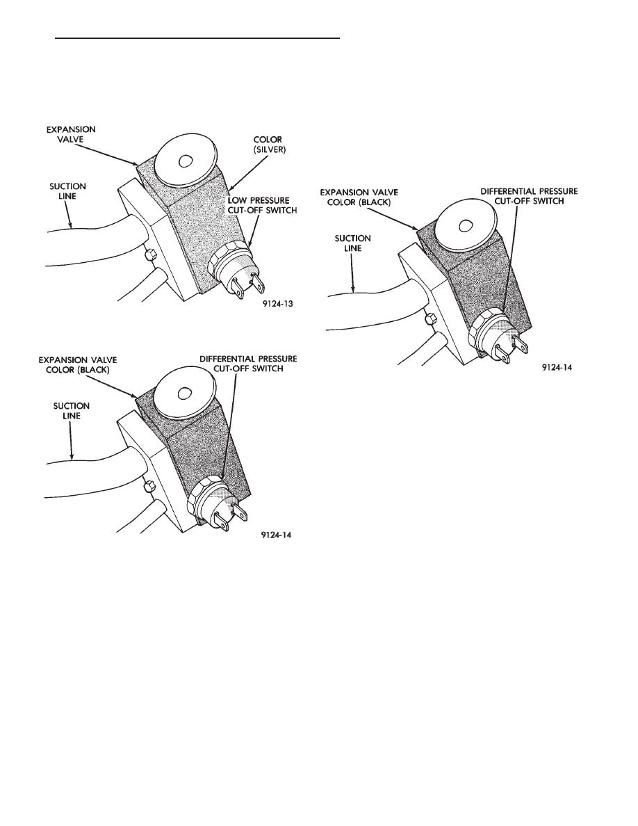
(3) Disconnect the wire connector at the differential
pressure cut-off switch. Using a jumper wire, jump
across the terminals inside the connector boot (Fig. 24).
(4) Close all doors, windows and vents to the passen-
ger compartment.
(5) Set heater-A/C control to A/C, full heat, FLOOR,
and high blower.
(6) Start the engine and hold the idle speed (1000
rpm). After the engine has reached running tempera-
ture, allow the passenger compartment to heat up.
This will create the need for maximum refrigerant flow
into the evaporator.
(7) Discharge (high pressure) gauge should read 965
to 1655 kPa (140 to 240 psi) when the refrigerant
charge is sufficient. If system cannot achieve proper
pressure, replace the expansion valve. If pressure is
correct, record reading and proceed with test.
WARNING: PROTECT SKIN AND EYES FROM CON-
TACTING CO
2
PERSONAL INJURY CAN RESULT.
(8) If discharge pressure is within specified range,
freeze the expansion valve control head (Fig. 8) for
30 seconds. Use a super cold substance (liquid
CO
2
).Do not spray R-12 Refrigerant on the expan-
sion valve for this test. Refer to Refrigerant
Recycling in the Refrigerant Service Procedures
section. If compressor discharge (high) pressure does
not drop by 15% or more than the pressure recorded in
step 7, replace the expansion valve. Allow the expan-
sion valve to thaw. The discharge pressure should
Fig. 22 Low Pressure Cut-Off Switch and Expansion
Valve—Typical
Fig. 23 Differential Pressure Cut-Off Switch and Ex-
pansion Valve—Typical
Fig. 24 Differential Pressure Cut-Out Switch
Ä
HEATING AND AIR CONDITIONING
24 - 55
stabilize to the pressure recorded in step 7. If the
pressure does not stabilize, replace the expansion
valve.
When expansion valve tests are complete, refer to
Heater and A/C Performance Tests and remove all test
equipment before returning vehicle to use.
SILVER EXPANSION VALVE TEST
Expansion valve tests should be performed af-
ter compressor tests.
Liquid CO
2
is required to test the expansion
valve. It is available from most welding supply
facilities. CO
2
is also available from companies
which service and sell fire extinguishers.
Review Safety Precautions and Warnings in the
General Information section of this Group. The work
area and vehicle must be 21°C to 27°C (70°F to 85°F)
when testing expansion valve. To test the expansion
valve:
(1) Connect a charging station or manifold gauge set
to the refrigerant system service ports.
(2) Verify the refrigerant charge level using the sight
glass method.
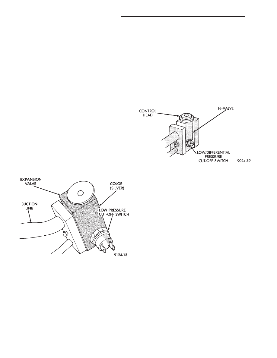
(3) Disconnect wire connector at low pressure cut-off
switch (Fig. 25). Using a jumper wire, jump terminals
inside wire connector boot.
(4) Close all doors, windows and vents to the passen-
ger compartment.
(5) Set heater-A/C control to A/C, full heat, FLOOR,
and high blower.
(6) Start the engine and hold the idle speed (1000
rpm). After the engine has reached running tempera-
ture, allow the passenger compartment to heat up.
This will create the need for maximum refrigerant flow
into the evaporator.
(7) If the refrigerant charge is sufficient, discharge
(high pressure) gauge should read 965 to 1655 kPa (140
to 240 psi). Suction (low pressure) gauge should read
140 kPa to 207 kpa (20 psi to 30 psi). If system
cannot achieve proper pressure readings, replace the
expansion valve. If pressure is correct, proceed with
test.
WARNING: PROTECT SKIN AND EYES FROM CON-
TACTING CO
2
PERSONAL INJURY CAN RESULT.
(8) If suction side low pressure is within specified
range, freeze the expansion valve control head (Fig. 26)
for 30 seconds. Use a super cold substance (liquid CO
2
).
Do not spray R-12 Refrigerant on the expansion
valve for this test. Suction side low pressure should
drop to -50 kPa (-15 in. Hg) If not, replace expansion
valve.
(9) Allow expansion valve to thaw. The low pressure
gauge reading should stabilize at 140 kPa to 240 kPa
(20 psi to 30 psi). If not, replace expansion valve.
When expansion valve test is complete, test A/C
overall performance. Refer to the Heater and A/C
Performance Test in this section. Remove all test
equipment before returning vehicle to use.
REMOVAL
WARNING: THE REFRIGERATION SYSTEM MUST BE
COMPLETELY EMPTY BEFORE PROCEEDING WITH
THIS OPERATION.
(1) Remove the boot-type wire connector from the
pressure cut-off switch.
(2) Remove the attaching bolt in center of refriger-
ant line-plumbing sealing plate (Fig. 27).
(3) Carefully pull the refrigerant line-sealing plate
assembly from the expansion valve towards front of
vehicle. Do Not scratch the expansion valve sealing
surfaces with pilot tubes.
(4) Cover the openings on A/C line-sealing plate
assembly to prevent contamination.
(5) Remove two screws securing the expansion valve
to the evaporator sealing plate.
(6) Carefully remove valve.
Fig. 25 Low Pressure Cut-Off Switch
Fig. 26 Expansion Valve
24 - 56
HEATING AND AIR CONDITIONING
Ä

INSTALLATION
(1) Remove and replace the aluminum gasket on
the evaporator sealing plate.
(2) Carefully hold the expansion valve to the evap-
orator sealing plate (do not scratch sealing surface).
Install two attaching screws and tighten to 11
6 3
N
Im (100 6 30 inch lbs.).
(3) Remove and replace the aluminum gasket (Fig.
15) on the refrigerant line-sealing plate assembly.
(4) Carefully hold the refrigerant line-sealing plate
assembly to the expansion valve, install bolt and
tighten to 23
6 3 NIm (200 6 30 inch lbs.).
(5) Connect wires to low pressure cut-off switch.
(6) Evacuate and recharge system.
(7) After expansion valve is installed, system is
charged, and leaks have been checked, repeat A/C
performance check.
FILTER-DRIER ASSEMBLY
REMOVAL AND INSTALLATION
WARNING: THE REFRIGERATION SYSTEM MUST
BE COMPLETELY EMPTY BEFORE PROCEEDING
WITH THIS OPERATION.
(1) Remove the two high pressure lines from the
sides of the filter-drier assembly (Fig. 1). Then care-
fully separate the lines from filter-drier. Discard old
gaskets.
(2) Cover the open ends of the A/C lines to mini-
mize system contamination.
(3) Remove two mounting strap bolts and lift the
filter-drier from vehicle. If replacing the filter-drier
assembly, transfer the mounting strap to replace-
ment part.
To install, replace both refrigerant line to filter-
drier gaskets, and reverse the preceding operation.
Evacuate and recharge system.
CONDENSER ASSEMBLY
The A/C condenser is mounted to the radiator with
bolts (upper) and mounting pads (lower).
WARNING: THE REFRIGERATION SYSTEM MUST BE
COMPLETELY REMOVED BEFORE PROCEEDING
WITH THIS OPERATION. REFER TO DISCHARGING
REFRIGERATION SYSTEM IN THIS GROUP.
REMOVAL AND INSTALLATION
(1) Using a refrigerant recovery machine, remove
the refrigerant from the A/C system.
(2) Remove the refrigerant line mounting nut (Fig.
2) and separate the refrigerant lines from condenser
sealing plate.
(3) Cover the open ends of the A/C lines and con-
denser to minimize system contamination.
(4) Remove the coolant overflow bottle, electric cool-
ing fans and radiator assembly. Also remove the turbo-
charger inter-cooler if equipped. Refer to Group 7,
Cooling System.
On some models, complete removal of the ra-
diator, or coolant drainage is not necessary. The
radiator may be moved slightly rearward to re-
move the condenser.
(5) Remove the two bolts securing the condenser
assembly to the radiator.
(6) Slip the condenser from the lower radiator
mounting brackets.
(7) Remove condenser.
To install, replace all O-rings and gaskets and coat
sealing surfaces with approved refrigerant oil. Then
reverse the preceding operation. When installing a
Fig. 27 Expansion Valve
Fig. 1 Filter-Drier—Typical
Ä
HEATING AND AIR CONDITIONING
24 - 57
Нет комментариевНе стесняйтесь поделиться с нами вашим ценным мнением.
Текст