Chrysler Le Baron, Dodge Dynasty, Plymouth Acclaim. Manual — part 15
• Clogged water passages in end cross overs and
clogged gas passages.
INTAKE MANIFOLD
INSTALLATION
(1) Clean all surfaces of cylinder block and cylin-
der heads.
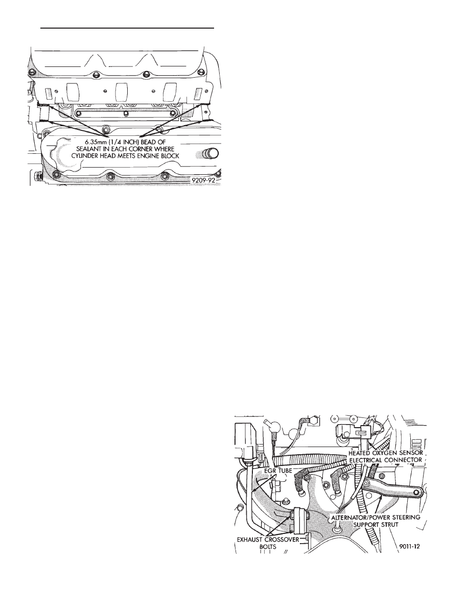
(2) Place a drop (about 1/4 in. diameter) of Mopar
Silicone Rubber Adhesive Sealant or equivalent, onto
each of the four manifold to cylinder head gasket
corners (Fig. 15).
WARNING: INTAKE MANIFOLD GASKET IS MADE
OF VERY THIN METAL AND MAY CAUSE PER-
SONAL INJURY, HANDLE WITH CARE.
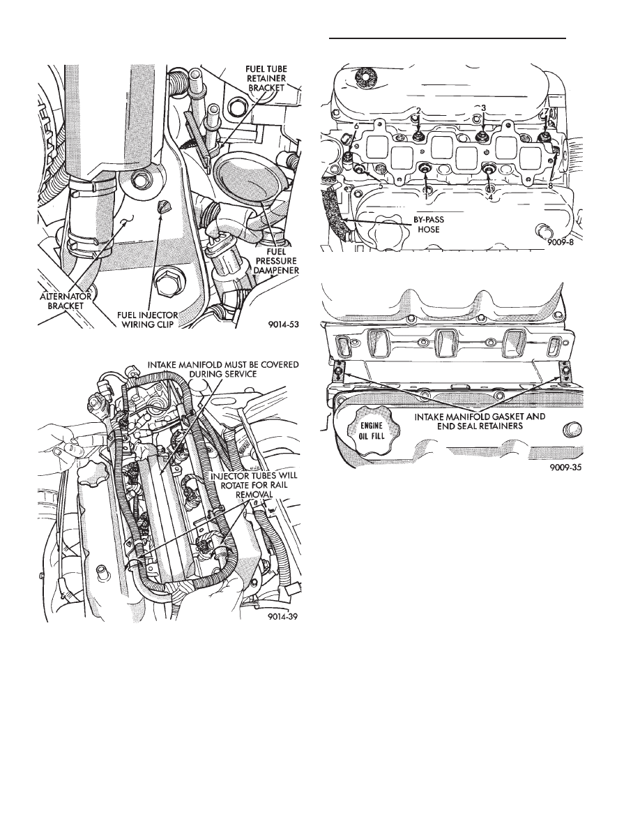
(3) Carefully install the intake manifold gasket
(Fig. 14). Tighten end seal retainer screws to 12 N
Im
(105 in. lbs.) torque.
(4) Install intake manifold and (8) bolts and
tighten to 1 N
Im (10 in. lbs.) torque. Then retighten
bolts to 22 N
Im (200 in. lbs.) torque in sequence
shown in (Fig. 13). Then retighten again to 22 N
Im
(200 in. lbs.)torque. After intake manifold is in place,
inspect to make sure seals are in place.
(5) Make sure the injector holes are clean and all
plugs have been removed.
(6) Lube injector O-ring with a drop of clean en-
gine oil to ease installation.
Fig. 11 Fuel Injector Wiring Clip
Fig. 12 Fuel Rail Removal
Fig. 13 Intake Manifold Removal and Installation
Fig. 14 Intake Manifold Gasket
11 - 22
EXHAUST SYSTEM AND INTAKE MANIFOLD
Ä
(7) Put the tip of each injector into their ports.
Push the assembly into place until the injectors are
seated in the ports (Fig. 12).
(8) Install the (4) fuel rail attaching bolts and
tighten to 22 N
Im (200 in. lbs.) torque (Fig. 10).
(9) Install fuel tube retaining bracket screw and
tighten to 4 N
Im (35 in. lbs.) torque (Fig. 10).
(10) Reconnect cam sensor, coolant temperature
sensor and engine temperature sensors (Fig. 11).
(11) Install fuel injector harness wiring clips on
the generator bracket and intake manifold water
tube (Fig. 11).
(12) Connect fuel pressure regulator vacuum line.
(13) Remove covering on lower intake manifold
and clean surface.
(14) Place intake manifold gasket on lower mani-
fold. Put upper manifold into place and install bolts
finger tight.
(15) Install the generator bracket to intake mani-
fold bolt and the cylinder head to intake manifold
strut bolts. Do not torque.
(16) Tighten intake manifold bolts to 28 N
Im (250
in. lbs.) torque in the sequence shown in (Fig. 9).
(17) Tighten generator bracket to intake manifold
bolt to 54 N
Im (40 ft. lbs.) torque (Fig. 8).
(18) Tighten the cylinder head to intake manifold
strut bolts to 54 N
Im (40 ft. lbs.) torque (Fig. 5).
(19) Connect ground strap, MAP and heated oxy-
gen sensor electrical connectors (Fig. 6).
(20) Connect charge temperature sensor electrical
connector (Fig. 5).
(21) Connect vacuum harness to intake plenum
(Fig. 5).
(22) Using a new gasket, connect the EGR tube
flange to the intake manifold and tighten to 22 N
Im
(200 in. lbs.) torque.
(23) Clip wiring harness into the hole in the throt-
tle cable bracket.
(24) Connect the wiring connectors to the throttle
position sensor TPS and automatic idle speed AIS
motor (Fig. 4).
(25) Connect vacuum harness to throttle body (Fig.
4).
(26) Install the direct ignition system DIS coils.
Tighten fasteners to 12 N
Im (105 in. lbs.) torque
(Fig. 8).
(27) Lubricate the ends of the chassis fuel tubes
with 30 wt oil. Connect fuel supply and return hoses
to chassis fuel tube assembly. pull back on the quick
connect fitting to ensure complete insertion (Fig. 7).
(Refer to Fuel Hoses, Clamps and Quick Connect Fit-
tings in Group 14 Fuel Systems).
(28) Install throttle cable (Fig. 3).
(29) Connect fuel injector wiring harness.
(30) Install air cleaner and hose assembly (Fig. 2).
(31) Connect negative battery cable. Fill Cooling
System. See Cooling System, Group 7.
(32) With the DRBII Scan Tool use ASD Fuel Sys-
tem Test to pressurize system to check for leaks.
CAUTION: When using the ASD Fuel System Test,
the Auto Shutdown (ASD) relay will remain ener-
gized for 7 minutes or until the ignition switch is
turned to the OFF position, or Stop All Test is se-
lected.
EXHAUST MANIFOLDS
REMOVAL
(1) Raise vehicle and disconnect exhaust pipe from
rear cowl side exhaust manifold at articulated joint.
(2) Separate EGR tube from rear manifold and dis-
connect Heated Oxygen Sensor lead wire (Fig. 16).
(3) Remove
Generator/Power
Steering
Support
Strut (Fig. 16).
(4) Remove bolts attaching cross-over pipe to man-
ifold (Fig. 16).
Fig. 15 Intake Manifold Gasket Sealing
Fig. 16 EGR Tube, Heated Oxygen Sensor and
Generator/Power Steering Strut
Ä
EXHAUST SYSTEM AND INTAKE MANIFOLD
11 - 23
(5) Remove bolts attaching rear manifold to cylin-
der head and remove manifold.
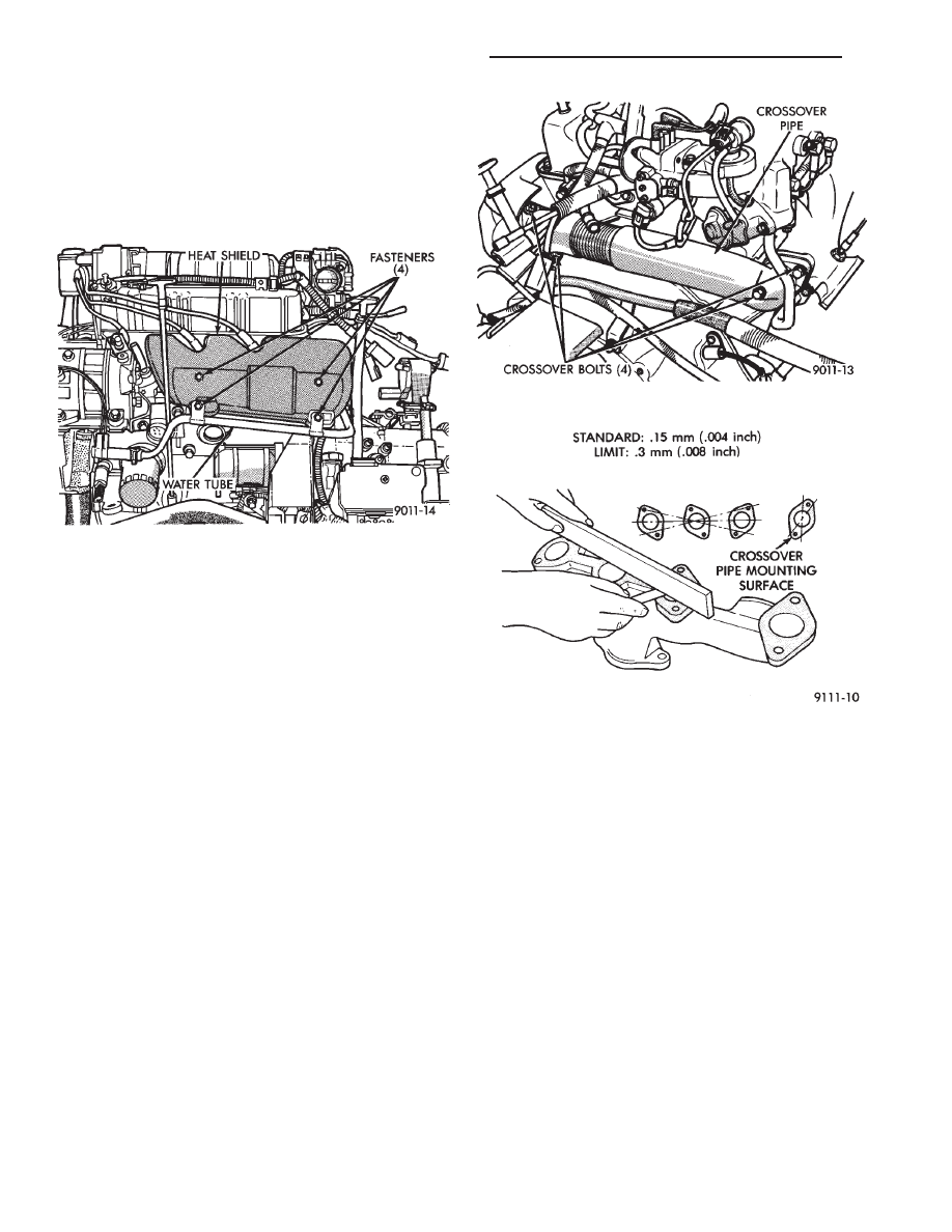
(6) Lower vehicle and remove screws attaching
front heat shield to front manifold (Fig. 17).
(7) Remove bolts fastening crossover pipe to front
exhaust manifold and nuts fastening manifold to cyl-
inder head. Remove assemblies (Fig. 18).
INSPECTION
Inspect exhaust manifolds for damage or cracks
and check distortion of the cylinder head mounting
surface and exhaust crossover mounting surface with
a straightedge and thickness gauge (Fig. 19).
EXHAUST MANIFOLD
INSTALLATION
(1) Install rear exhaust manifold and tighten at-
taching bolts to 23 N
Im (200 in. lbs.) torque.
(2) Attach exhaust pipe to exhaust manifold and
tighten shoulder bolt to 28 N
Im (250 in. lbs.) torque.
(3) Attach crossover pipe to exhaust manifold and
tighten bolt to 33 N
Im (25 ft. lbs.) torque and connect
heated oxygen sensor lead (Fig. 16).
(4) Install EGR Tube and Generator/Power Steer-
ing Strut (Fig. 16).
(5) Install front exhaust manifold and attach ex-
haust crossover (Fig. 18).
(6) Install front manifold heat shield and tighten
attaching screws to 23 N
Im (200 in. lbs.) torque (Fig.
17).
Fig. 17 Heat Shield
Fig. 18 Crossover Pipe
Fig. 19 Check Exhaust Manifold Mounting Surface
11 - 24
EXHAUST SYSTEM AND INTAKE MANIFOLD
Ä
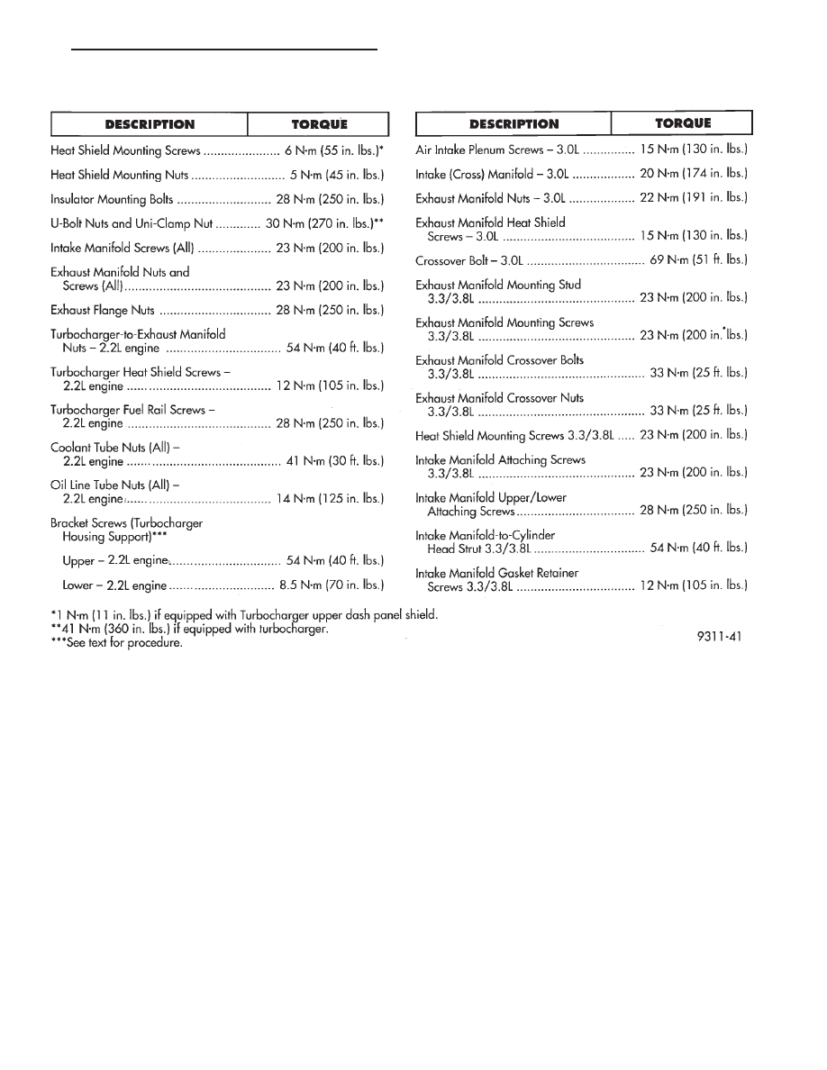
TORQUE SPECIFICATION
Ä
EXHAUST SYSTEM AND INTAKE MANIFOLD
11 - 25
Нет комментариевНе стесняйтесь поделиться с нами вашим ценным мнением.
Текст