Chrysler Le Baron, Dodge Dynasty, Plymouth Acclaim. Manual — part 32
Radiator Fan Relay
A/C Clutch Relay
Auto Shutdown Relay
Purge Solenoid
S/C Servo Solenoids
Generator Field
Tachometer Output
Torque Converter Clutch Solenoid (3 speed auto-
matic transaxle only)
EGR Solenoid
All Solenoids/Relays
ASD Fuel System Test
Speed Control Vacuum Solenoid
Speed Control Vent Solenoid
THROTTLE BODY MINIMUM AIR FLOW CHECK
PROCEDURE
(1) Connect DRBII scan tool.
(2) Remove air cleaner assembly. Plug the heated
air door vacuum hose.
(3) Warm engine in Park or Neutral until the cool-
ing fan has cycled on and off at least once.
(4) Hook-up timing check device and tachometer.
(5) Disconnect the coolant temperature sensor and
set basic timing to 12°BTDC
6 2°BTDC.
(6) Shut off engine. Reconnect coolant temperature
sensor.
(7) Disconnect the PCV valve hose from the intake
manifold nipple.
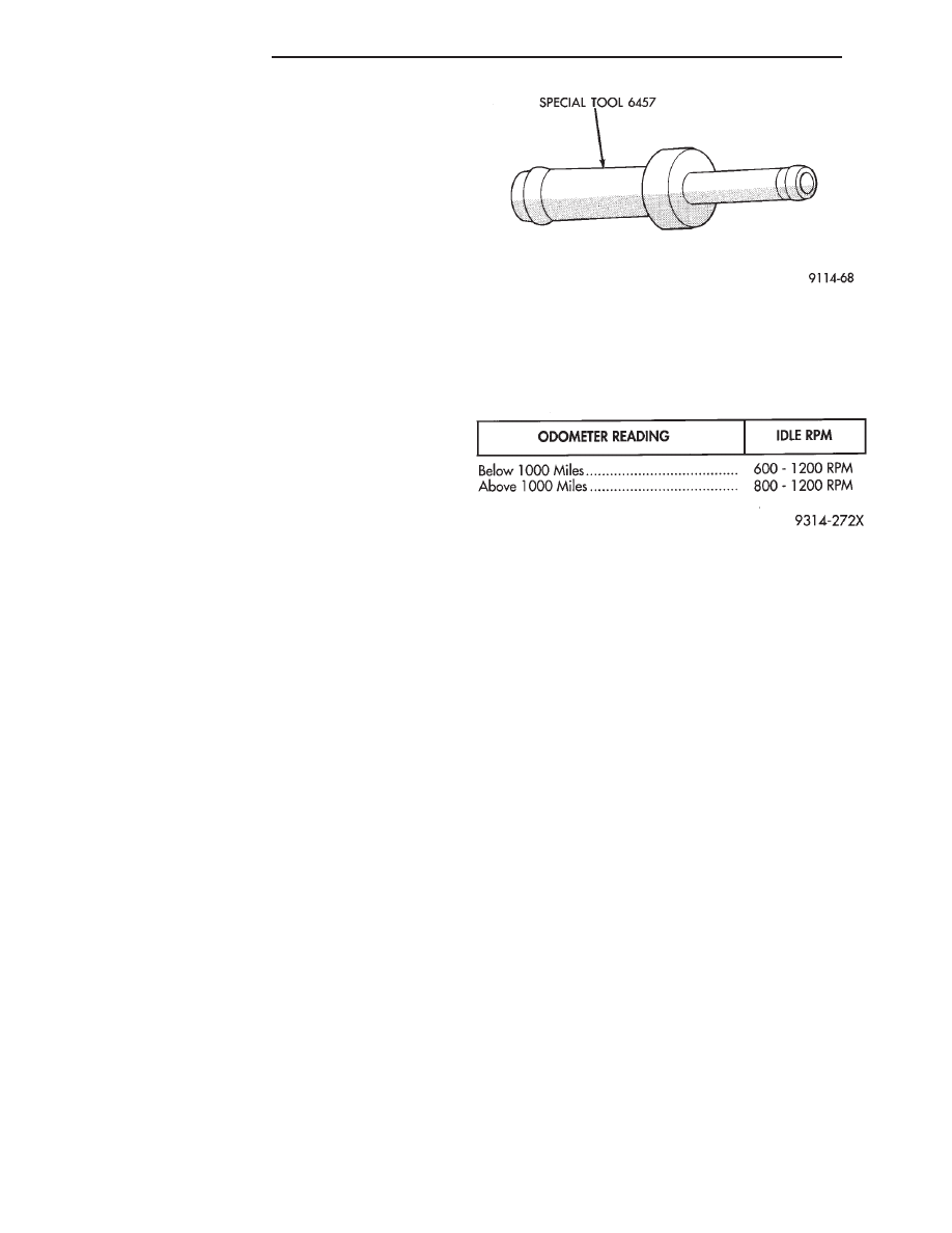
(8) Attach Air Metering Fitting #6457 (Fig. 4) to
the intake manifold PCV nipple.
(9) Restart the engine, allow engine to idle for at
least one minute.
(10) Using the DRBII scan tool, Access Min Air-
flow Idle Spd in the sensor read test mode.
(11) The following will then occur:
• Idle air control motor will fully close.
• Idle spark advance will become fixed.
• Idle fuel will be provided at a set value.
• Engine RPM will be displayed on DRBII scan tool.
(12) Check idle RPM with tachometer. If idle RPM
is within the specifications listed below, then the
throttle body minimum air flow is set correctly.
If idle RPM is not within specification replace
throttle body.
(13) Shut off engine.
(14) Remove Special Tool number 6457 from in-
take manifold PCV nipple. Reinstall the PCV valve
hose.
(15) Remove DRBII scan tool.
(16) Reinstall
air
cleaner
assembly.
Reinstall
heated air door vacuum hose.
(17) Disconnect timing check device and tachome-
ter.
IGNITION TIMING PROCEDURE
Refer to Group 8D Ignition System
60-WAY PCM WIRING CONNECTOR
Refer to the powertrain control module (PCM) wir-
ing connector descriptions for information regarding
wire colors and cavity numbers (Fig. 5).
Fig. 4 Air Metering Fitting
IDLE SPECIFICATIONS
14 - 46
FUEL SYSTEMS
Ä

Fig.
5
PCM
W
iring
Connector
Cavity
Description
Ä
FUEL SYSTEMS
14 - 47
2.2L/2.5L SINGLE POINT FUEL INJECTION—SERVICE PROCEDURES
INDEX
page
page
Canister Purge Solenoid
. . . . . . . . . . . . . . . . . . . 53
Electric Exhaust Gas Recirculation Transducer (EET)
Service
. . . . . . . . . . . . . . . . . . . . . . . . . . . . . . . 53
Fuel Fitting
. . . . . . . . . . . . . . . . . . . . . . . . . . . . . 50
Fuel Injector
. . . . . . . . . . . . . . . . . . . . . . . . . . . . 51
Fuel Lines and Hoses
. . . . . . . . . . . . . . . . . . . . . 48
Fuel Pressure Regulator
. . . . . . . . . . . . . . . . . . . 51
Fuel System Pressure Release Procedure
. . . . . . 48
Heated Oxygen Sensor (O
2
Sensor)
. . . . . . . . . . 54
Idle Air Control Motor
. . . . . . . . . . . . . . . . . . . . . 53
Manifold Absolute Pressure Sensor
. . . . . . . . . . . 53
PCM Service
. . . . . . . . . . . . . . . . . . . . . . . . . . . . 54
Throttle Body
. . . . . . . . . . . . . . . . . . . . . . . . . . . . 48
Throttle Position Sensor
. . . . . . . . . . . . . . . . . . . 52
FUEL LINES AND HOSES
Perform the Fuel System Pressure Relief Procedure
before servicing the fuel system. The procedure must
be done to bleed fuel pressure from the system before
removing clamps or hoses.
Use care when removing fuel hoses to prevent dam-
age to hose or hose nipple. Always use new hose
clamps, of the correct type, during reassembly. Tighten
hose clamps to 1 N
Im (10 in. lbs.) torque. Do not use
aviation style clamps on this system or hose
damage may result.
FUEL SYSTEM PRESSURE RELEASE PROCEDURE
CAUTION: Before servicing the fuel pump, fuel lines,
fuel filter, throttle body, or fuel injector, release fuel
system pressure.
(1) Loosen fuel filler cap to release fuel tank pres-
sure.
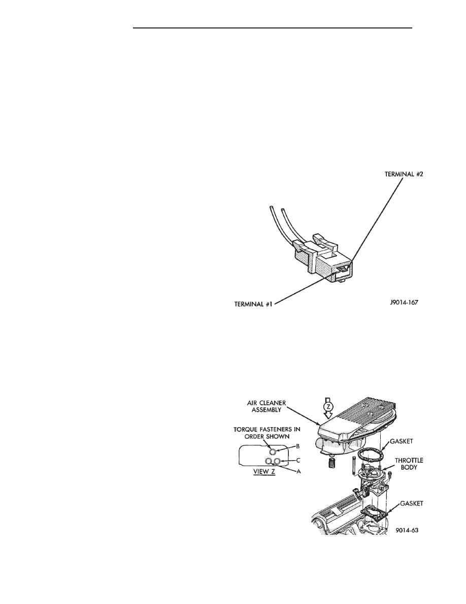
(2) Disconnect injector wiring harness connector at
edge of throttle body (Fig. 1).
(3) Connect a jumper wire between terminal Num-
ber 1 of the injector harness and engine ground.
(4) Connect a jumper wire to the positive terminal
Number 2 of the injector harness and touch the battery
positive post for no longer than 5 seconds. This
releases system pressure.
(5) Remove jumper wires.
(6) Continue fuel system service.
THROTTLE BODY
CAUTION: The fuel system is under a constant pres-
sure of 270 kPa (39 psi). When servicing the fuel
portion of the throttle body, release fuel pressure
before disconnecting any tubes. Refer to the fuel
pressure release procedure.
Always reassemble throttle body components with
new O-rings and seals where applicable. Never use
silicone lubricants on O-rings or seals, damage may
result. Use care when removing fuel tubes to prevent
damage to quick connect fittings or tube ends. Refer
to Fuel Hoses, Clamps, and Quick Connect Fittings
in the Fuel Delivery Section of this Group.
REMOVAL
(1) Remove air cleaner (Fig. 2).
(2) Perform fuel system pressure release procedure.
(3) Disconnect negative battery cable.
(4) Disconnect vacuum hoses and electrical connec-
tors (Fig. 3).
Fig. 1 Injector Harness Connector
Fig. 2 Throttle Body and Air Cleaner Assembly
14 - 48
FUEL SYSTEMS
Ä

Fig.
3
Throttle
Body
Ä
FUEL SYSTEMS
14 - 49
Нет комментариевНе стесняйтесь поделиться с нами вашим ценным мнением.
Текст