Chrysler Le Baron, Dodge Dynasty, Plymouth Acclaim. Manual — part 330
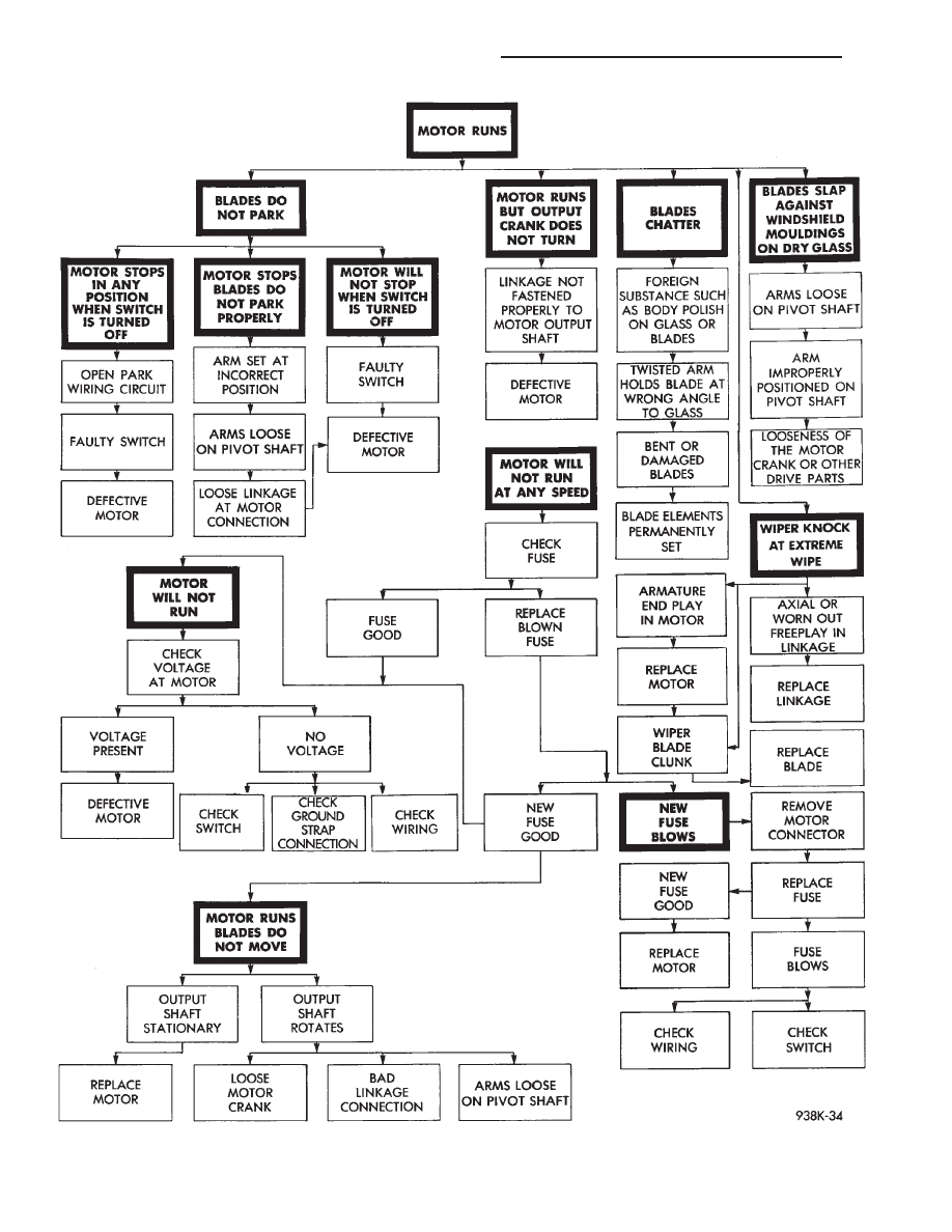
Fig. 9 Windshield Wiper Motor Diagnosis
8K - 4
WINDSHIELD WIPER AND WASHER SYSTEMS
Ä
CONDITION: MOTOR RUNS SLOWLY AT ALL
SPEEDS
PROCEDURE
(1) Disconnect wiring harness connector at motor.
Remove wiper arms and blades. Connect an ammeter
between battery (B+) and terminal 3 on motor (Fig.
11).
(a) If motor runs and average ammeter reading
is more than 6 amps, proceed to step 2.
(b) If motor runs and average ammeter reading
is less than 6 amps, proceed to step 3.
(2) Check to see if wiper linkage or pivots are
binding or caught. Disconnect drive link from motor.
(a) If motor now runs and draws less than 3
amps, repair linkage system.
(b) If motor continues to draw more than 3 amps,
replace motor assembly.
(3) Check motor wiring harness for shorting be-
tween high and low speed wires as follows:
(a) Connect a voltmeter or test lamp to motor
ground strap.
(b) Set wiper switch to LOW position.
(c) Connect other lead of voltmeter to terminal 4
of the wiring harness.
(d) If voltage is present, there is a short in the
wiring or wiper switch. If no voltage is present pro-
ceed to step e.
(e) Set wiper switch to HIGH position.
(f) Move voltmeter lead from terminal 4 to termi-
nal 3 of the wiring harness.
(g) If voltage is present, there is a short in the
wiring or wiper switch.
CONDITION: MOTOR WILL RUN AT HIGH
SPEED, BUT NOT AT LOW SPEED. MOTOR
WILL RUN AT LOW SPEED, BUT NOT AT HIGH
SPEED
PROCEDURE
(1) If motor will not run on high speed, put switch
in HIGH position and connect a test lamp between
motor Terminal 4 and ground (Fig. 12).
(2) If motor will not run on low speed, put switch
in LOW position and connect a test lamp between
motor Terminal 3 and ground.
(3) If test lamp does not light at motor terminal,
there is an open in wiring or switch. If test lamp
lights at motor terminal, replace motor assembly.
CONDITION: MOTOR WILL KEEP RUNNING
WITH SWITCH IN OFF POSITION
PROCEDURE
Remove wiring harness. Connect jumper from Ter-
minal 1 to Terminal 3 of wiper motor (Fig. 13). Con-
nect second jumper from Terminal 2 to battery (B+).
If motor runs to PARK position and stops, wiper
switch is faulty. If motor keeps running and does not
park, replace motor assembly.
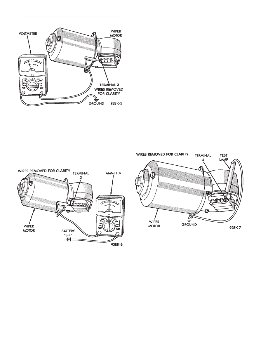
Fig. 10 Voltmeter Between Terminal 3 and Ground
Fig. 11 Ammeter Between Terminal 3 and Battery
Fig. 12 Test Lamp Between Terminal 4 and Ground
Ä
WINDSHIELD WIPER AND WASHER SYSTEMS
8K - 5
CONDITION: MOTOR WILL STOP WHEREVER
IT IS, WHEN COLUMN SWITCH IS PUT IN OFF
POSITION. THE WIPERS DO NOT CONTINUE
RUNNING TO PARK POSITION
PROCEDURE
(1) Remove motor wiring connector and clean ter-
minals. Reconnect connector and test motor.If prob-
lem persists, proceed to Step 2.
(2) Set wiper switch to OFF position. Disconnect
motor wiring connector. Connect a voltmeter or test
lamp to the motor ground strap. Connect the other
lead to terminal 2 of wiring connector.
(a) If voltage is not present, check for an open
circuit in the wiring harness or wiper control
switch.
(b) If voltage is present, proceed to step 3.
(3) Connect an ohmmeter or continuity tester be-
tween terminals 3 and 1 (Fig. 14).
(a) If there is continuity between these termi-
nals, the problem is a defective motor.
(b) If there is no continuity, the problem is an
open circuit in the wiper control switch or wiring
harness.
REAR WIPER MOTOR—AG BODY TEST
The following test is used in order to locate and
then repair liftgate wiper motor defects. Refer to
Group 8W, Wiring Diagrams for liftgate wiper motor
wiring schematic.
(1) Remove lower cover on liftgate (Fig. 15).
(2) Disconnect feed connector from wiper motor.
(3) With ignition switch in ON position, check for
battery voltage at blue wire.
(4) With ignition switch in ON position and wiper
switch ON, check for battery voltage at blue and
brown wire. If battery voltage is not present in steps
3 and 4, check fuse, liftgate wiper switch and wiring.
(5) With ignition switch in ON position, and wiper
switch in OFF position, check for battery voltage be-
tween blue and brown wires. If battery voltage is not
present, check ground wire to liftgate switch.
(6) If battery voltage is present in steps 3 and 4,
replace motor.
FRONT WIPER MOTOR ASSEMBLY—AG and AJ
BODIES
REMOVAL
(1) Park system.
(2) Open the hood assembly.
(3) Remove wiper arms and blades, disconnect
hoses from tee connector (Fig. 16).
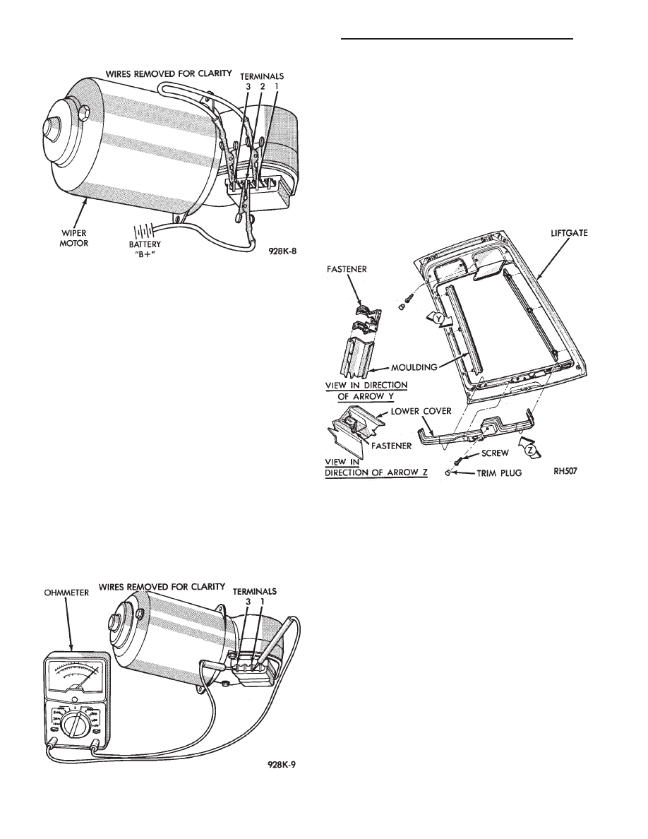
Fig. 13 One Jumper Wire Between Terminal 1 and 3.
One Jumper Wire Between Terminal 2 and Battery
positive
Fig. 14 Ohmmeter Between Terminals 3 and 1
Fig. 15 Liftgate Lower Cover
8K - 6
WINDSHIELD WIPER AND WASHER SYSTEMS
Ä

Fig.
16
W
indshield
W
iper
Motor
and
Linkage—AG
and
AJ
Bodies
Ä
WINDSHIELD WIPER AND WASHER SYSTEMS
8K - 7
Нет комментариевНе стесняйтесь поделиться с нами вашим ценным мнением.
Текст