Chrysler Le Baron, Dodge Dynasty, Plymouth Acclaim. Manual — part 328
(3) Remove both upper and lower steering column
shrouds.
(4) Remove multi-function switch tamper proof
mounting screws (Fig.7).
(5) Gently pull switch away from column. Loosen
connector screw. The screw will remain in the con-
nector.
(6) Remove wiring connector from multi-function
switch.
INSTALLATION
(1) Install wiring connector to switch and tighten
connector retaining screw to 2 N
Im (17 in. lbs.)
torque.
(2) Mount multi-function switch to column and
tighten retaining screws to 2 N
Im (17 in. lbs.) torque.
(3) Install steering column covers. Tighten retain-
ing screws to 2 N
I (17 in. lbs.) torque.
(4) Tilt column only install tilt lever.
(5) Install negative battery cable.
(6) Check all functions of switch for proper opera-
tion.
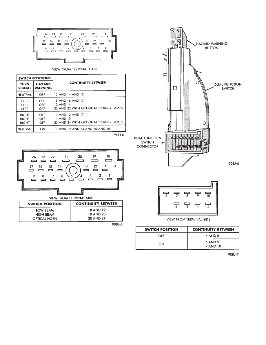
Fig. 2 Turn Signal and Hazard Switch Continuity
Fig. 3 Beam Select Switch Continuity
Fig. 4 Dual-Function Switch Connector
Fig. 5 Hazard Warning Switch Continuity—AJ Body
8J - 4
TURN SIGNALS AND HAZARD WARNING FLASHER
Ä
DUAL-FUNCTION SWITCH—AG AND AJ BODIES
REMOVAL
(1) Disconnect negative battery cable.
(2) Tilt column only remove tilt lever.
(3) Remove three attaching screws, in the upper
and lower steering column covers and remove covers.
(4) Remove two tamper proof mounting screws.
(5) Gently pull switch away from column. Release
connector lock on the wiring connector, then remove
the connector from the switch (Fig. 8).
INSTALLATION
(1) Install wiring connector to switch. Make sure
that switch locking tab is fully seated in the wiring
connector.
(2) Mount switch to column and tighten screws to
2 N
I (17 in. lbs.) torque.
(3) Install steering column covers and tighten
screws to 2 N
I (17 in. lbs.) torque.
(4) Tilt column only install tilt lever.
(5) Re-install negative battery cable.
(6) Check all functions of switch for proper opera-
tion of the hazard warning and turn signal cancella-
tion.
REMOTE TURN SIGNAL SWITCH REMOVAL—AG
AND AJ BODIES
(1) Disconnect battery ground cable..
(2) Remove turn signal lever by pulling it straight
out of the switch (Fig. 9).
(3) Remove two screws from the bottom of the
switch pod that hold turn signal switch.
(4) Disconnect turn signal pigtail wire from head-
lamp switch at the 8-way connector.
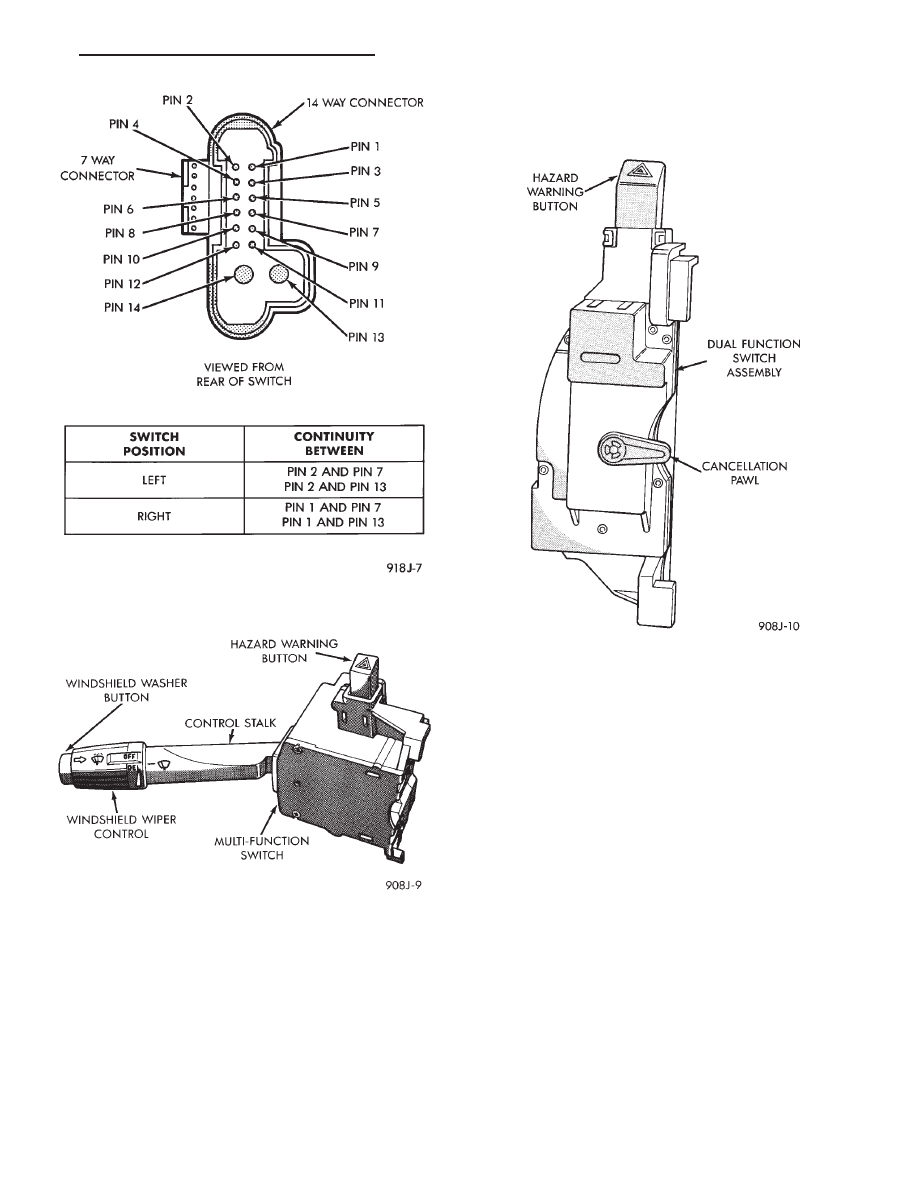
Fig. 6 Remote Turn Signal Switch Continuity—AG
and AJ Bodies
Fig. 7 Multi-Function Switch—AA, AC, AP and AY
Bodies
Fig. 8 Dual-Function Switch—AG and AJ Bodies
Ä
TURN SIGNALS AND HAZARD WARNING FLASHER
8J - 5

(5) For installation reverse above procedure.
(6) Check for proper operation of all components
which are controlled by the pod mounted switch.
TURN SIGNAL AND HAZARD WARNING FLASHER
LOCATION
AA, AC, AP AND AY BODIES
The turn signal flasher and the hazard warning
flasher are two separate plug-in type units.
On AC and AY both flashers are on the relay mod-
ule (Fig. 10).
On AA and AP Bodies the hazard flasher is located
on the relay module (Fig. 11). The turn signal flasher
is on the driver’s side of A/C duct for AA Body (Fig.
12) and center A/C duct for AP Body.
AG AND AJ BODIES
The turn signal flasher and the hazard warning
flasher are combined into one unit called a combina-
tion flasher (combo-flasher). The combo-flasher con-
trols the flashing of the hazard warning system and
the turn signal system. An inoperative bulb or in-
complete turn signal circuit will result in an increase
in flasher speed.
The combo-flasher is located under the instrument
panel, right of the steering column and is clipped on
the A/C distribution duct. The combo-flasher is yel-
low in color for ease of identification.
TURN SIGNAL RELAYS—AG AND AJ BODIES
The AG and AJ models are equipped with four
turn signal relays.
Fig. 9 Remote Turn Signal Switch—AG and AJ
Bodies
Fig. 10 Turn Signal and Hazard Warning
Flasher—AC and AY Bodies
Fig. 11 Hazard Warning Flasher—AA and AP Bodies
Fig. 12 Turn Signal Flasher—AA Body
8J - 6
TURN SIGNALS AND HAZARD WARNING FLASHER
Ä
One relay controls the right rear turn signal and
stop lamp. The second relay controls the left rear
turn signal and stop lamp. The third relay controls
the right front turn signal. The fourth relay controls
the left front turn signal.
The turn signal relays are located in the relay
bank, underneath the driver’s side of the instrument
panel. The four turn signal relays are identical and
can be interchanged.
The turn signal relays do not cycle on and off with
the turn signal lamp. Their function is to complete
the turn signal circuit when the turn signal is
switched on. Turn signal cycling is done by the com-
bination flasher.
To test the relay, remove the suspect relay and
switch it with 1 of the other 3 turn signal relays. If
the problem follows the relay, replace that relay. If
the problem remains in the same circuit, the relay is
not the problem. Refer to Group 8W, Wiring Dia-
grams.
Ä
TURN SIGNALS AND HAZARD WARNING FLASHER
8J - 7
Нет комментариевНе стесняйтесь поделиться с нами вашим ценным мнением.
Текст