Chrysler Le Baron, Dodge Dynasty, Plymouth Acclaim. Manual — part 329
WINDSHIELD WIPER AND WASHER SYSTEMS
CONTENTS
page
page
GENERAL WIPER INFORMATION
. . . . . . . . . . . 1
INTERMITTENT WINDSHIELD WIPER MOTOR
AND SWITCH SERVICE PROCEDURES
. . . . 12
WINDSHIELD WASHERS
. . . . . . . . . . . . . . . . . 17
WINDSHIELD WIPER BLADE AND ARM SERVICE
PROCEDURES
. . . . . . . . . . . . . . . . . . . . . . . . . 1
WINDSHIELD WIPER MOTOR AND LINKAGE
ASSEMBLY SERVICE PROCEDURES
. . . . . . . 3
GENERAL WIPER INFORMATION
WARNING: ON VEHICLES EQUIPPED WITH AIR-
BAG, SEE GROUP 8M, RESTRAINT SYSTEMS FOR
STEERING WHEEL OR COLUMN REMOVAL PROCE-
DURES.
The windshield wipers can be operated with the
windshield wiper switch only when the ignition
switch is in the ACCESSORY or IGNITION position.
A fuse, located in the fuse block, protects the cir-
cuitry of the wiper system and the vehicle.
The wiper motor has permanent magnet fields. The
speeds are determined by current flow to the appro-
priate set of brushes.
The intermittent wipe system, in addition to low
and high speed, has a delay mode. The delay mode
has a range of 2 to 15 seconds. This is accomplished
by a variable resistor in the wiper switch and is con-
trolled electrically by a relay.
The wiper system completes the wipe cycle when
the switch is turned OFF. The blades park in the
lowest portion of the wipe pattern.
WINDSHIELD WIPER BLADE AND ARM SERVICE PROCEDURES
WIPER BLADES
Wiper blades, exposed to the weather for a long pe-
riod of time, tend to lose their wiping effectiveness.
Periodic cleaning of the wiper blade is suggested to
remove the accumulation of salt and road film. The
wiper blades, arms, and windshield should be cleaned
with a sponge or cloth and a mild detergent or nona-
brasive cleaner. If the blades continue to streak or
smear, they should be replaced.
WIPER BLADE ELEMENT CHANGE
(1) Turn wiper switch ON, position blades to a con-
venient place by turning the ignition switch ON and
OFF.
(2) Lift wiper arm to raise blade off glass.
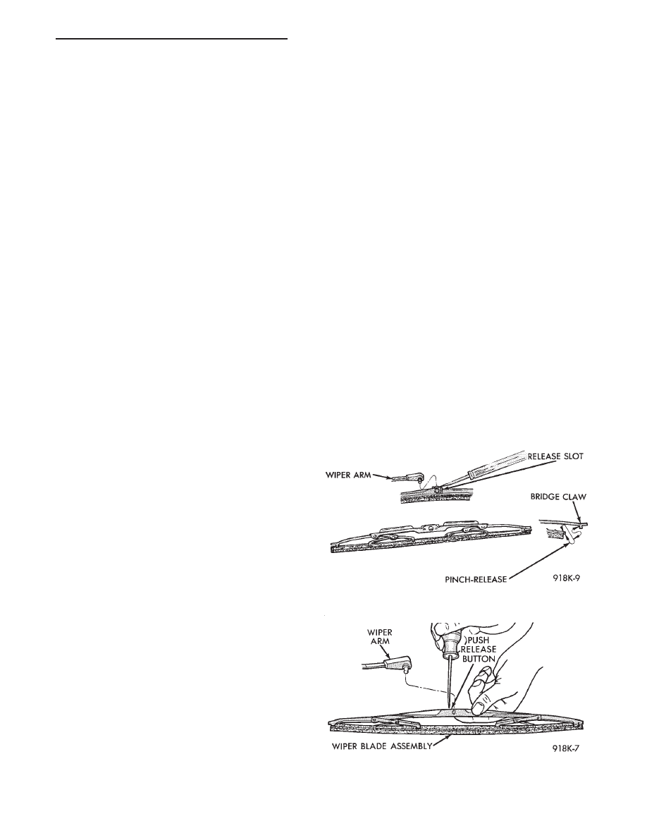
(3) Remove blade assembly from arm by inserting
a small screwdriver blade into release slot of wiper
blade and push downward (Fig. 1 and 2), or push re-
lease button (2).
(4) To remove wiping element from blade assem-
bly:
• Place blade assembly on a working surface
• Apply pressure backwards to open up the blade as-
sembly (Fig. 3)
• By pushing downward and pulling away remove
the wiping element, or lift tab on one end links and
squeeze link to remove from center bridge.
Fig. 1 Wiper Blade and Element
Fig. 2 Blade Assembly from Arm
Ä
WINDSHIELD WIPER AND WASHER SYSTEMS
8K - 1
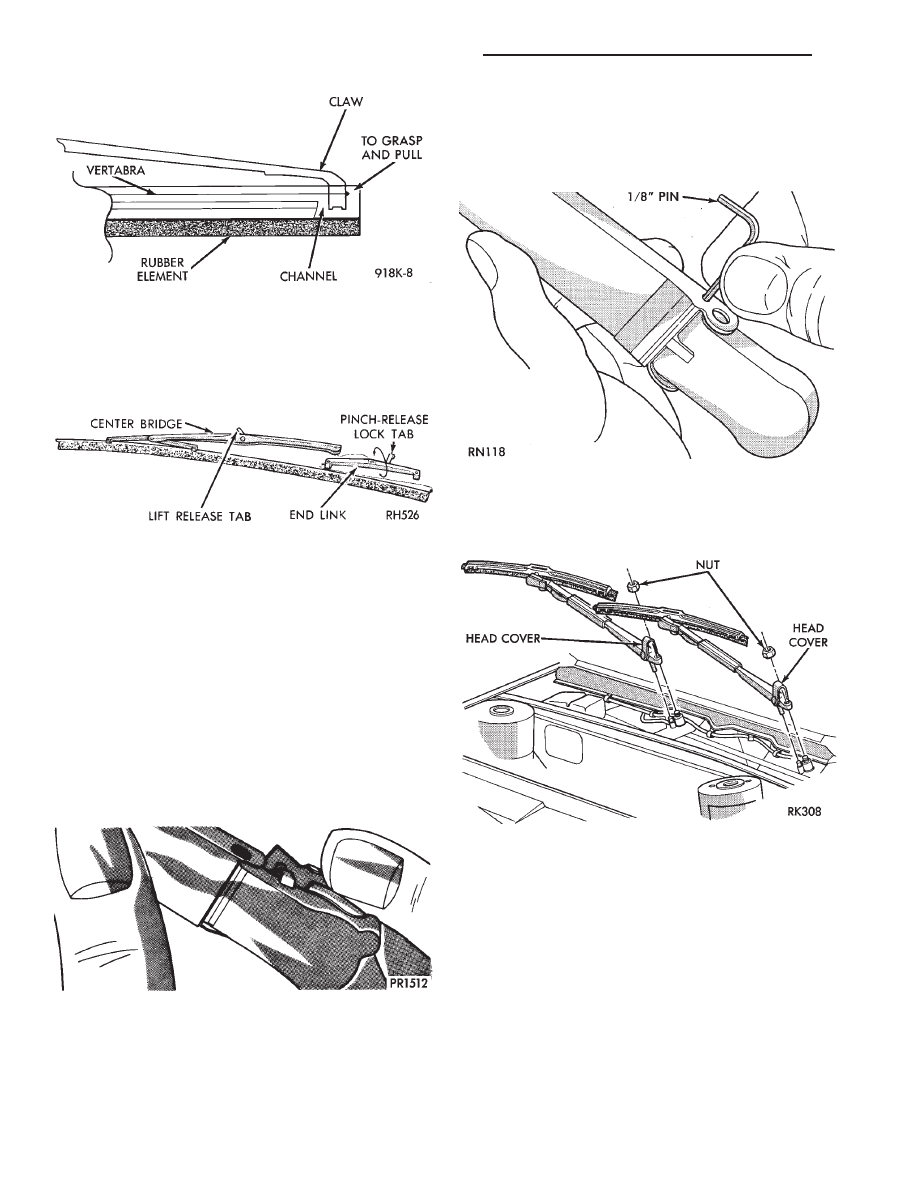
• Slide end link off element from claws of other link
(Fig. 4), or by grasping the rubber element where the
channel is and pull the element out for replacement.
(5) To install reverse above procedures.
(6) Check each bridge claw for positive locking
when installing blade element, and blade assembly
for positive locking.
WIPER ARM REPLACEMENT
AG AND AJ BODIES
REMOVAL
Lift the arm to permit the latch (Fig. 5) to be
pulled out to the holding position then release the
arm. Arm front will remain off windshield in this po-
sition. Remove the arm from the pivot using a rock-
ing motion.
INSTALLATION
For proper installation of wiper arm, refer to Wiper
Arm Adjustment.
AA, AC, AP AND AY BODIES
REMOVAL
(1) Lift the wiper arm and place a 3.17mm (1/8
inch) pin into the arm pin hole (Fig. 6).
(3) Remove the wiper arm from the pivot using a
rocking motion.
INSTALLATION
(1) Clean the wiper pivot shaft of any metal filings
using a wire brush.
(2) Position wiper arm so that the blade tip is
19.05 mm (3/4 inch) from the top of the cowl screen.
Fig. 3 Wiper Element
Fig. 4 Wiping Element from Blade Assembly
Fig. 5 Removing Wiper Arm—AG and AJ Bodies
Fig. 6 Removing Wiper Arm—AA, AC, AP and AY
Bodies 16
(2) Lift the head cover (Fig. 7) and remove the
wiper arm attaching nut.
Fig. 7 Wiper Arm Head Cover and Nut—AA, AC, AP
and AY Bodies
8K - 2
WINDSHIELD WIPER AND WASHER SYSTEMS
Ä
(3) Secure arm to pivot with attaching nut and
tighten 17 to 22 N
Im (155 to 195 in. lbs.) torque.
(4) Close head cover and remove pin from arm pin
hole.
WIPER ARM ADJUSTMENT
FRONT ARM ADJUSTMENT
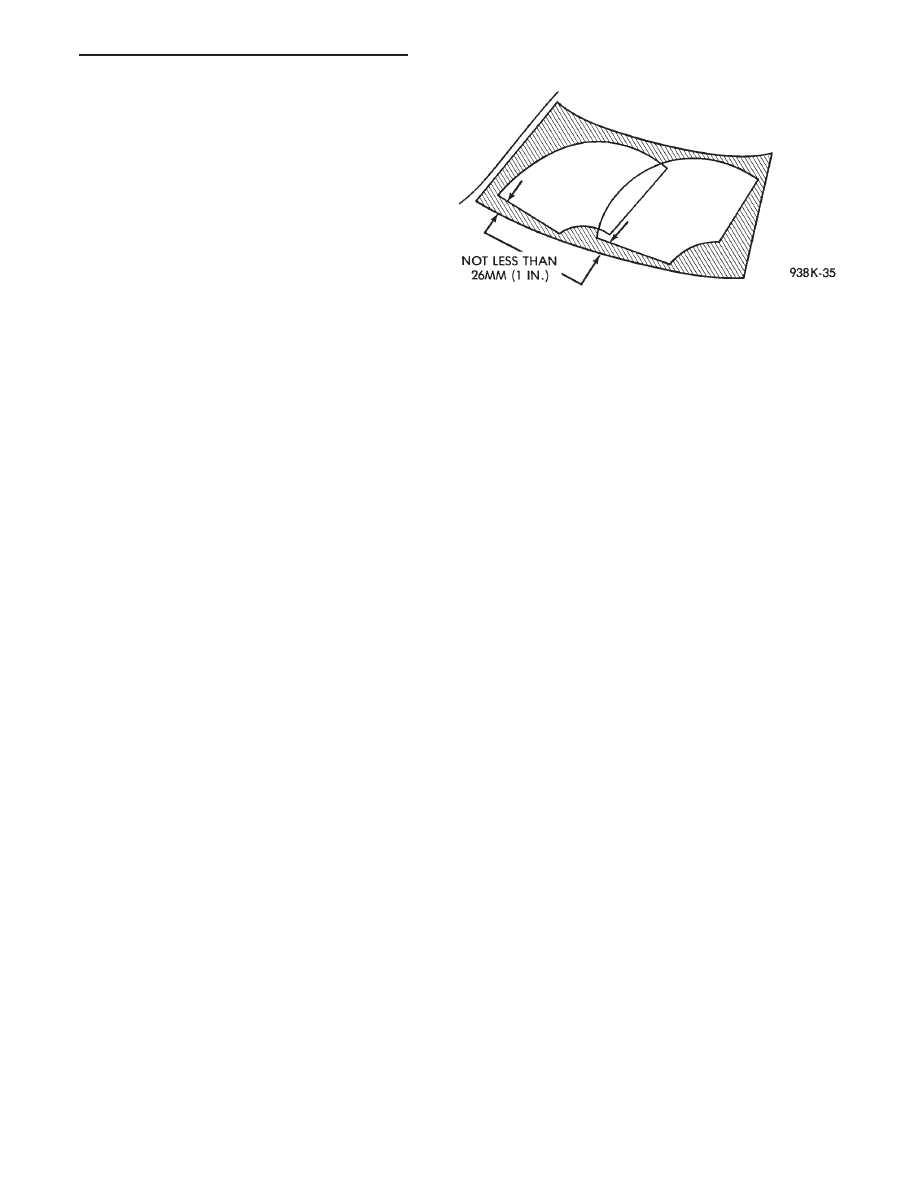
(1) Cycle the wiper motor into the PARK position.
(2) Check the tips of the blades in blackout area.
From the bottom edge of the windshield to the blade
should be no closer than 25 mm (1 inch) (Fig. 8).
(3) Operate the wipers if the requirements are not
met, check linkage and pivot assembly for worn
parts.
REAR ARM ADJUSTMENT
With the motor in the park position, mount the
arm on the motor shaft. Choose a serration engage-
ment that positions the blade, parallel with the bot-
tom edge of the liftgate glass.
WINDSHIELD WIPER MOTOR AND LINKAGE ASSEMBLY SERVICE PROCEDURES
INDEX
page
page
Front Wiper Motor Assembly—AG and AJ Bodies
. 6
Rear Wiper Motor Assembly—AG Body
. . . . . . . . 8
Rear Wiper Motor—AG Body Test
. . . . . . . . . . . . 6
Wiper Motor and Linkage Assembly—AA, AC, AY
Bodies
. . . . . . . . . . . . . . . . . . . . . . . . . . . . . . . . 8
Wiper Motor and Linkage Assembly—AP Body
. . 10
Wiper Motor System Test Procedures
. . . . . . . . . . 3
WIPER MOTOR SYSTEM TEST PROCEDURES
WARNING: ON VEHICLES EQUIPPED WITH AIR-
BAG, SEE GROUP 8M, RESTRAINT SYSTEMS FOR
STEERING WHEEL OR COLUMN REMOVAL PROCE-
DURES.
Whenever a wiper motor malfunction occurs, first
verify that the wiper motor wire harness is properly
connected to all connectors before starting normal di-
agnosis and repair procedures. Refer to Wiper Motor
Diagnosis Chart (Fig. 9).
The following is a list of general wiper motor sys-
tem problems, the tests that are to be performed to
locate the faulty part, and the corrective action to be
taken. These tests will cover both two speed and in-
termittent wipe functions.
TWO SPEED MOTOR FUNCTION TESTS
CONDITION: MOTOR WILL NOT RUN IN ANY
SWITCH POSITION
PROCEDURE
(1) Check for a blown fuse in the fuse block.
(a) If fuse is good, proceed to step 2.
(b) If fuse is defective, replace and check motor
operation in all switch positions.
(c) If motor is still inoperative and the fuse does
not blow, proceed to step 2.
(d) If replacement fuse blows, proceed to step 5.
(2) Place switch in LOW speed position.
(3) Listen to motor. If you cannot hear it running,
proceed to Step 4. If you hear it running, check motor
output shaft. If output shaft is not turning, replace
motor assembly. If it is turning, drive link to output
shaft or linkage is not properly connected. Replace
worn parts and/or properly connect drive link to the
motor output shaft.
(4) Connect a voltmeter between motor terminal 3
and ground strap (Fig. 10). If there is no voltage or very
little voltage (less than one volt) present, move nega-
tive test lead from the ground strap to negative battery
terminal.
(a) If an increase in voltage is noticed, the problem
is a bad ground circuit. Make sure the motor mount-
ing is free of paint and that nuts or bolts are tight.
(b) If there is still no indication of voltage, the
problem is an open circuit in the wiring harness or
wiper switch.
(c) If no more than 3 volts increase in voltage is
observed, the problem is a faulty motor assembly.
(5) Disconnect motor wiring connector and replace
fuse.
(a) If fuse does not blow, motor is defective.
(b) If fuse blows, switch or wiring is at fault.
Fig. 8 Windshield Wiper Arm Adjustment
Ä
WINDSHIELD WIPER AND WASHER SYSTEMS
8K - 3
Нет комментариевНе стесняйтесь поделиться с нами вашим ценным мнением.
Текст