Chrysler Le Baron, Dodge Dynasty, Plymouth Acclaim. Manual — part 165
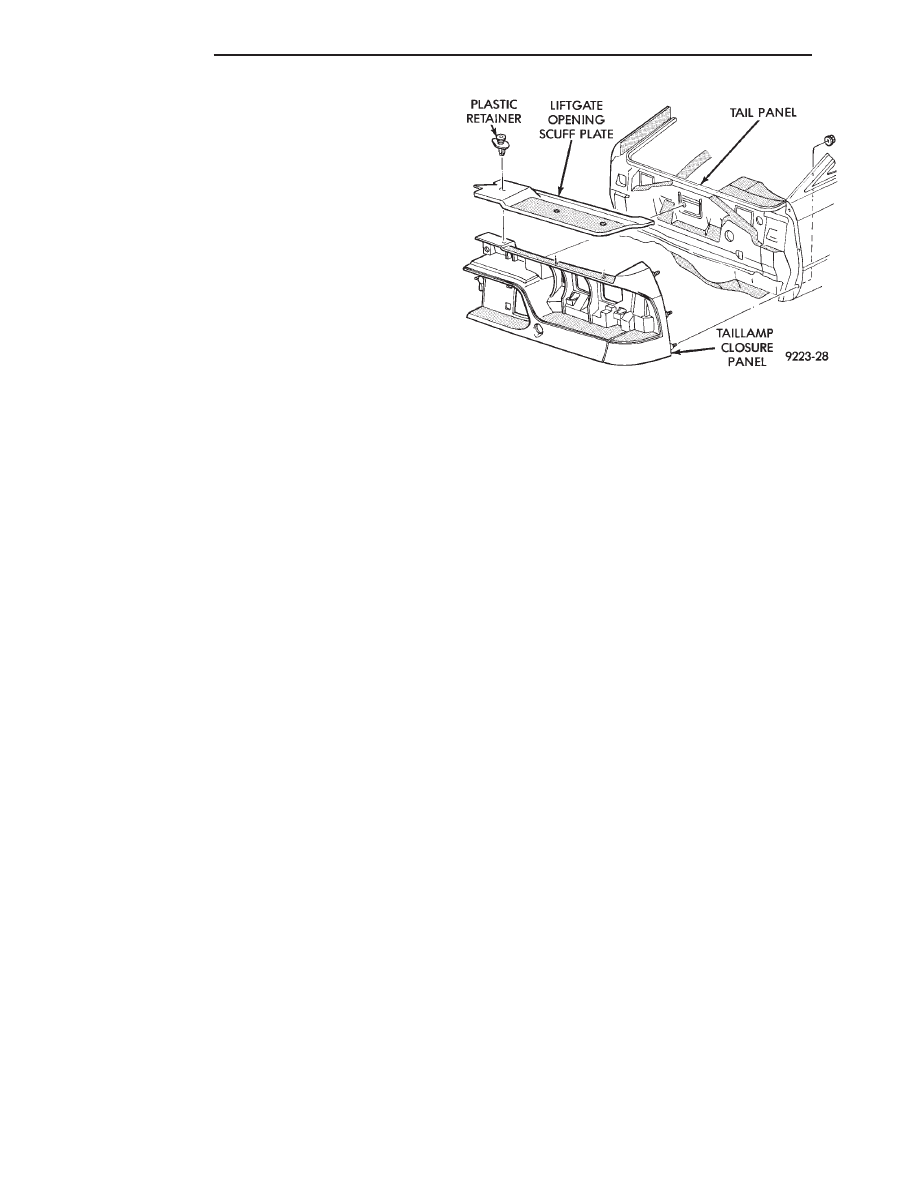
(5) Remove bolt holding quarter panel spoiler to
tail lamp closure panel, if equipped.
(6) Remove tail lamps and license plate lamps, re-
fer to Group 8L, Lamps for proper procedures.
(7) Remove nuts holding tail lamp closure panel to
tail panel.
(8) Remove nuts holding tail lamp closure panel to
quarter panel ends.
(9) Separate tail lamp closure panel from vehicle.
INSTALLATION
Reverse the preceding operation.
Fig. 46 Tail Lamp Closure Panel
23 - 70
AG-BODY
Ä
AJ-VEHICLE BODY COMPONENT SERVICE
INDEX
page
page
A-Pillar and Roof Rail Mouldings
. . . . . . . . . . . . . . . . . . . . . . . . . . . . . 73
Cowl Panel Trim and Scuff Plates
. . . . . . . . . . . . . . . . . . . . . . . . . . . . . 76
Door Glass Lift Plate and Guide Post
. . . . . . . . . . . . . . . . . . . . . . . . . . . . . 75
. . . . . . . . . . . . . . . . . . . . . . . . . 74
. . . . . . . . . . . . . . . . . . . . . . . . . . . . 80
. . . . . . . . . . . . . . . . . . . . . 79
. . . . . . . . . . . . . . . . . . . . . 75
Front Door Silencer and Water Shield
. . . . . . . . . . . . . . . . . . 73
. . . . . . . . . . . . . . . . . . . . . . . . . 78
. . . . . . . . . . . . . . . . . . . . . . . . . . . . . 78
. . . . . . . . . . . . . . . . . . . . . . . . . . . 84
Glass Run Weatherstrip—AJ-21 Body
. . . . . . . . . . . . . . . . . . . . . . . . . . . . . . . . . . 71
. . . . . . . . . . . . . . . . . . . . . 71
. . . . . . . . . . . . . . . . . . . . . . 71
. . . . . . . . . . . . . . . . . . . . . . . . . . . . . 81
. . . . . . . . . . . . . . . . . . . . . . . . 72
. . . . . . . . . . . . . . 72
. . . . . . . . . . . . . . . . 76
. . . . . . . . . . . . . . . . . . . . . . . . . . . . . 71
Outside Door Latch Release Handle
. . . . . . . . . . . . . . . . . . . . . . . . 80
. . . . . . . . . . . . . . . . . . 76
. . . . . . . . . . . . . . . 77
. . . . . . . . . . . . . . . . . . . . . 85
. . . . . . . . . . . . . . . . . . . . . . . 77
. . . . . . . . . . . . . . . . . . . . . . . . . . 78
. . . . . . . . . . . . . . . . . . . . . . . . . . . . . 79
. . . . . . . . . . . . . . . . . . . . . 78
. . . . . . . . . . . . . . . . . . . . . . 81
. . . . . . . . . . . . . . . . . . . . 81
. . . . . . . . . . . . . . . . . . . . 81
. . . . . . . . . . . . . . . . . . . . 81
. . . . . . . . . . . . . . . . . . . . . . . . . . . . . . 82
Trunk Lid and Fuel Fill Door Release Cables
. . . . . . . . . . . . . . . . . . . . . . . . . 82
. . . . . . . . . . . . . . . . . . . . . . . . . . 83
. . . . . . . . . . . . . . . . . . . . . . . . . . 83
. . . . . . . . . . . . . . . . . . . 83
. . . . . . . . . . . . . . . . . . . . . 83
. . . . . . . . . . . . . . . . 83
. . . . . . . . . . . . . . . . . . . . . . . . 75
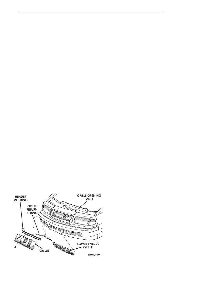
GRILLE
REMOVAL (FIG. 1)
(1) Remove screws holding grille to header mold-
ing at top of grille.
(2) Push downward on top of bumper fascia to gain
clearance for grille removal.
(3) Push grille downward and pull outward.
(4) Separate grille from vehicle.
INSTALLATION
Reverse the preceding operation.
GRILLE HEADER MOLDING
REMOVAL (FIG. 1)
(1) Remove grille.
(2) Remove nuts holding header molding to grille
opening panel.
(3) Separate header molding from vehicle.
INSTALLATION
Reverse the preceding operation.
LOWER GRILLE
REMOVAL (FIG. 1)
(1) Remove screws holding lower grille to fascia.
(2) Separate lower grille from vehicle.
INSTALLATION
Reverse the preceding operation.
GRILLE OPENING PANEL
REMOVAL (FIG. 2)
(1) Remove front bumper and fascia.
(2) Remove grille.
(3) Remove headlamp modules.
(4) Remove bolt holding grille opening panel to
bracket forward of radiator.
(5) Raise hood and remove push-in fasteners hold-
ing sight shields to closure panel. Separate sight
shields from vehicle.
Fig. 1 Grille Assembly
Ä
AJ-BODY
23 - 71
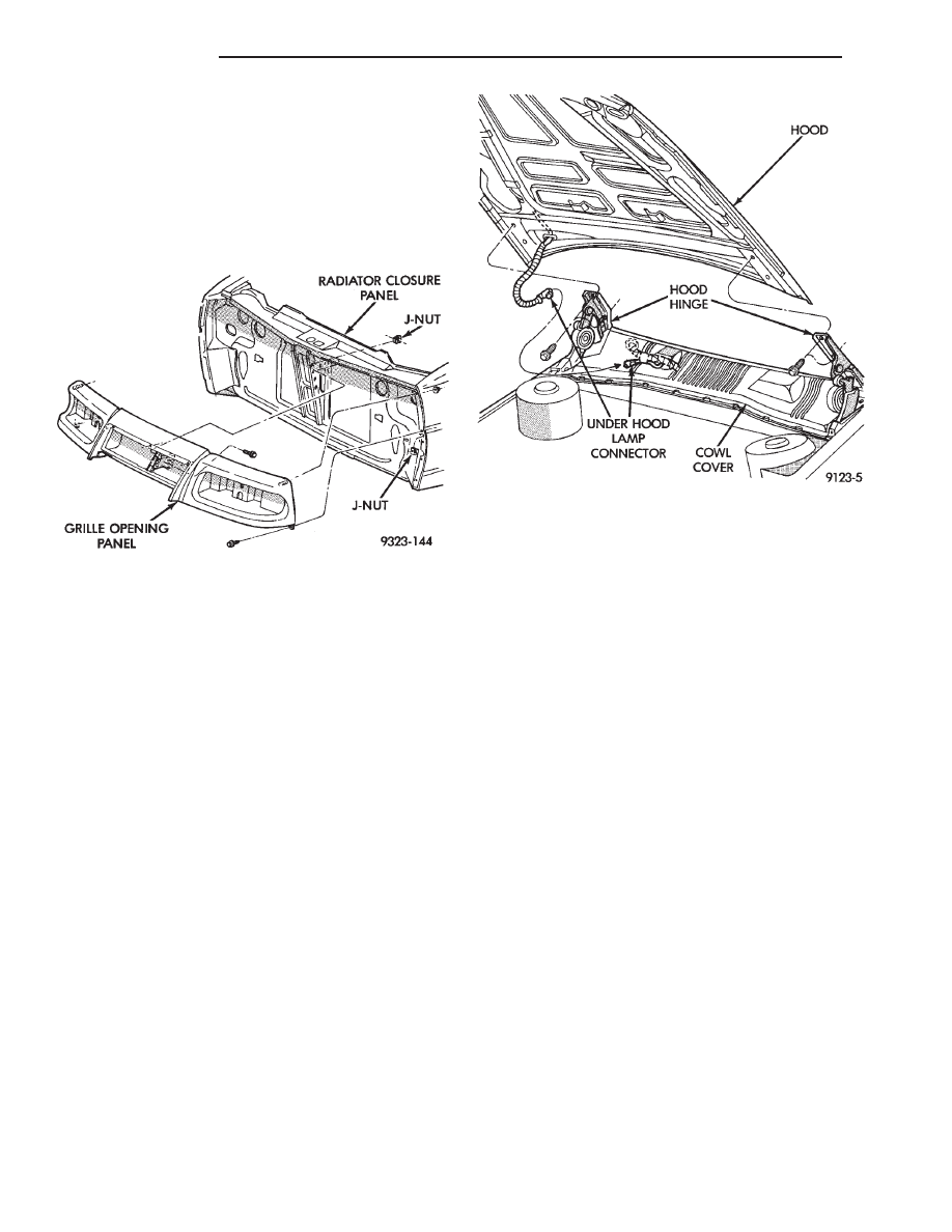
(6) Remove nuts holding grille opening panel to
front fenders.
(7) Remove bolts holding grille opening panel to
front fenders.
(8) Separate grille opening panel form vehicle.
INSTALLATION
Reverse the preceding operation. Align grille open-
ing panel to fit flush across fender joining locations.
HOOD AND HINGES
HOOD REMOVAL (FIG. 2)
(1) Raise hood to full up position.
(2) Lift front edge of cowl cover on the right side of
the windshield washer bottle and disconnect the un-
der hood lamp wire connector.
(3) Mark all bolt and hinge attachment locations
with a grease pencil or other suitable device to pro-
vide reference marks for installation. When install-
ing hood, align all marks and secure bolts. The hood
should be aligned to 4 mm (0.160 in.) gap to the front
fenders and flush across the top surfaces along fend-
ers.
(4) Remove the top hood to hinge attaching bolts
and loosen the bottom bolts until they can be re-
moved by hand.
(5) With assistance of a helper at the opposite side
of the vehicle to support the hood, remove the bottom
hood to hinge attaching bolts. Separate the hood
from the vehicle.
HOOD INSTALLATION
Reverse the preceding operation.
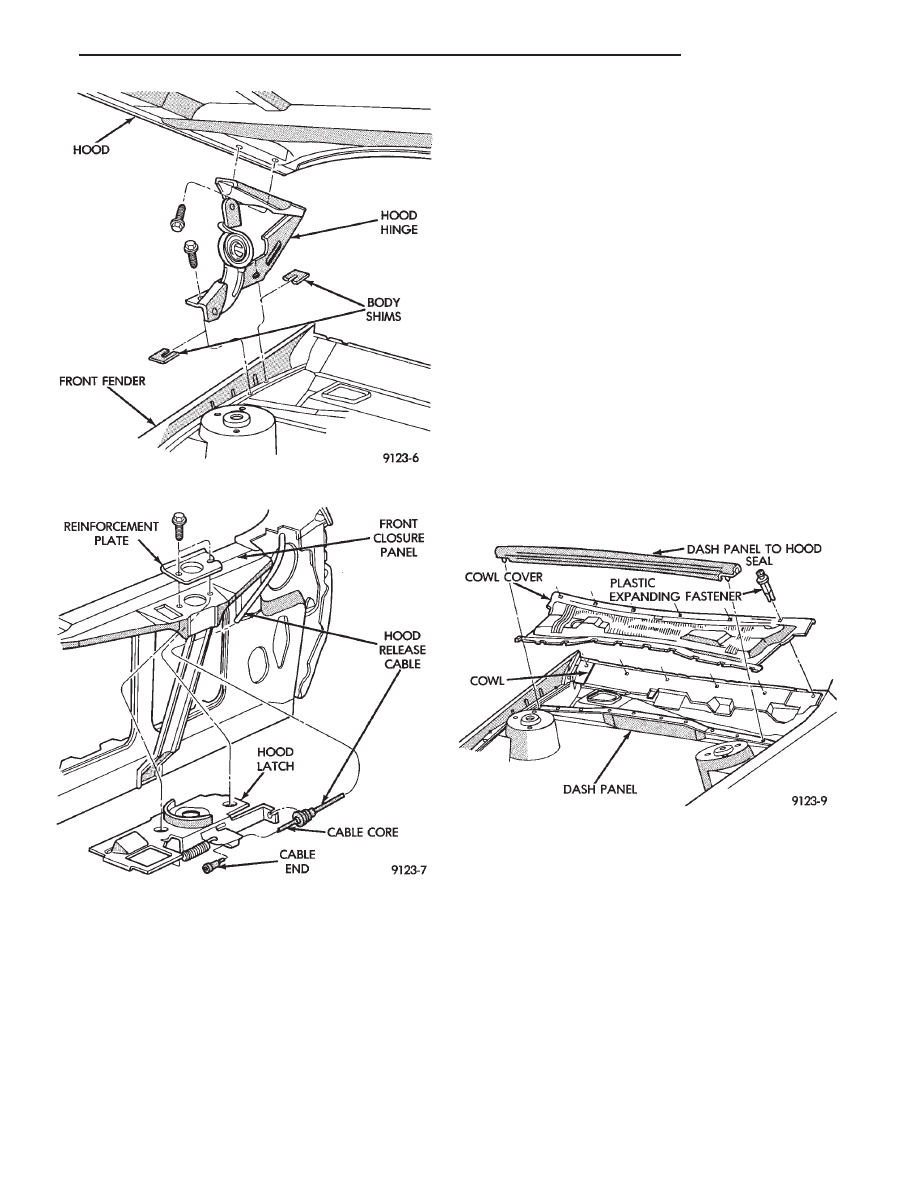
HOOD HINGE REMOVAL (FIG. 3)
(1) Support hood on the side that requires hinge
replacement.
(2) Mark all bolt and hinge attachment locations
with a grease pencil or other suitable device to pro-
vide reference marks for installation. When install-
ing hood hinge, align all marks and secure bolts. The
hood should be aligned to 4 mm (0.160 in.) gap to the
front fenders and flush across the top surfaces along
fenders. Shims can be added or removed under hood
hinge to achieve proper hood height.
(3) Remove hood to hinge attaching bolts.
(4) Remove hood hinge to front fender attaching
bolts and separate hinge from vehicle.
HOOD HINGE INSTALLATION
Reverse the preceding operation. If necessary, paint
new hinge before installation.
HOOD LATCH AND RELEASE CABLE
HOOD LATCH REMOVAL (FIG. 4)
(1) Raise hood to the full up position.
(2) Remove hood latch attaching bolts holding
latch to radiator closure panel and separate from ve-
hicle.
(3) Pry release cable casing attachment from slot
receiver on latch, disengage cable end from latch arm
hook.
HOOD LATCH INSTALLATION
Reverse the preceding operation.
HOOD LATCH RELEASE CABLE REMOVAL
(1) Raise hood to the full up position.
(2) Remove push-in fasteners holding hood latch
cover to radiator closure panel and separate cover
from vehicle.
(3) Disconnect hood release cable casing and cable
end from hood latch assembly. Refer to Hood Latch
Removal procedure in this section.
Fig. 2 Grille Opening Panel
Fig. 2 Hood Assembly Remove or Install—Typical
23 - 72
AJ-BODY
Ä
(4) Remove hood latch release cable handle attach-
ing bolts from under left lower edge of instrument
panel.
(5) Disengage release cable rubber grommet from
engine compartment dash panel behind instrument
panel.
(6) Rout cable assembly through engine compart-
ment around battery, under fender lip, under relay
bank, and under wiring harnesses, toward dash
panel. Push cable through access hole in dash panel
under the brake master cylinder, into passenger com-
partment.
HOOD LATCH RELEASE CABLE
INSTALLATION
Reverse the preceding operation.
COWL COVER
REMOVAL (FIG. 5)
(1) Raise hood to full up position.
(2) Disconnect windshield washer hoses from wiper
arms.
(3) Remove windshield wiper arm assemblies. Re-
fer to Group 8K, Windshield Wiper and Washer Sys-
tems.
(4) Remove plastic expanding type fasteners hold-
ing cowl cover to cowl, below windshield.
(5) Lift back of cowl cover and slide cover rearward
from under dash panel to hood seal and separate
cover from vehicle.
INSTALLATION
Reverse the preceding operation.
FRONT END SPLASH SHIELDS
FRONT WHEELHOUSE SPLASH SHIELD
REMOVAL (FIG. 6)
(1) Hoist vehicle and support on suitable safety
stands.
(2) Remove front wheel assembly.
(3) Remove push-in fasteners holding front wheel-
house splash shield to fender opening lip and inner
wheelhouse area.
(4) Separate wheelhouse splash shield from vehi-
cle.
FRONT WHEELHOUSE SPLASH SHIELD
INSTALLATION
Reverse the preceding operation.
Fig. 3 Hood Hinge Assembly—Typical
Fig. 4 Hood Latch Assembly—Typical
Fig. 5 Cowl Cover Assembly
Ä
AJ-BODY
23 - 73
Нет комментариевНе стесняйтесь поделиться с нами вашим ценным мнением.
Текст