Chrysler Le Baron, Dodge Dynasty, Plymouth Acclaim. Manual — part 164
(7) After urethane has cured remove masking tape
and water test to verify repair. Verify rear window
defogger operation, refer to Group 8N, Rear Window
Defogger.
QUARTER GLASS MODULE
REMOVAL (FIG. 36)
(1) Remove quarter trim panel as necessary to
gain access to quarter glass module.
(2) Remove nuts holding quarter glass module to
quarter glass opening.
(3) Cut urethane bonding around perimeter of
quarter glass opening fence.
(4) Push quarter glass module from quarter glass
opening.
(5) Separate module from vehicle.
INSTALLATION
(1) Clean hardened urethane from quarter glass
opening fence and glass module, if module replace-
ment is not required.
(2) Prepare fence and module using method de-
scribed in the Windshield section of this group.
(3) Reverse the removal operation.
ROOF SEAM MOLDING
REMOVAL (FIG. 37)
(1) Remove upper quarter trim panel.
(2) Remove head lining as necessary to gain access
to inside roof panel.
(3) Remove seal nut holding seam molding to roof
panel.
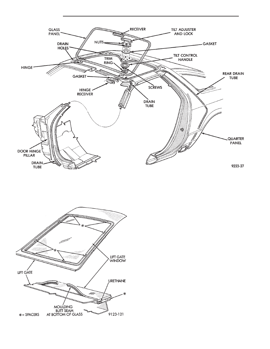
Fig. 34 Sunroof
Fig. 35 Lift Gate Window Glass
23 - 66
AG-BODY
Ä
(4) Separate molding from roof panel.
INSTALLATION
Reverse the preceding operation.
QUARTER PANEL SPOILER
REMOVAL (FIG. 38)
(1) Remove access cover from lift gate opening end
of quarter panel spoiler.
(2) Remove bolt holding spoiler to tail lamp closure
panel.
(3) Remove quarter trim panel.
(4) Remove nuts holding spoiler to quarter panel
from behind quarter panel above rear wheelhouse
(Fig. 38).
(5) Separate spoiler from vehicle.
INSTALLATION
Reverse the preceding operation.
LIFT GATE SPOILER
REMOVAL (FIG. 39)
(1) Raise lift gate to the up position.
(2) Remove nuts holding spoiler to outboard pinch
flanges of lift gate.
(3) Separate spoiler from lift gate.
INSTALLATION
Reverse the preceding operation.
LIFT GATE PROP CYLINDER
REMOVAL (FIG. 40)
(1) raise lift gate to the full open position.
(2) Support lift gate on a suitable lifting device.
(3) Remove bolt holding bottom of lift gate prop
cylinder to c-pillar.
(4) Remove bolt holding top of lift gate prop cylin-
der to lift gate.
(5) Separate prop cylinder from vehicle.
INSTALLATION
Reverse the preceding operation.
LIFT GATE
REMOVAL (FIG. 41)
(1) Raise lift gate to the full open position.
(2) Remove rear roof header molding.
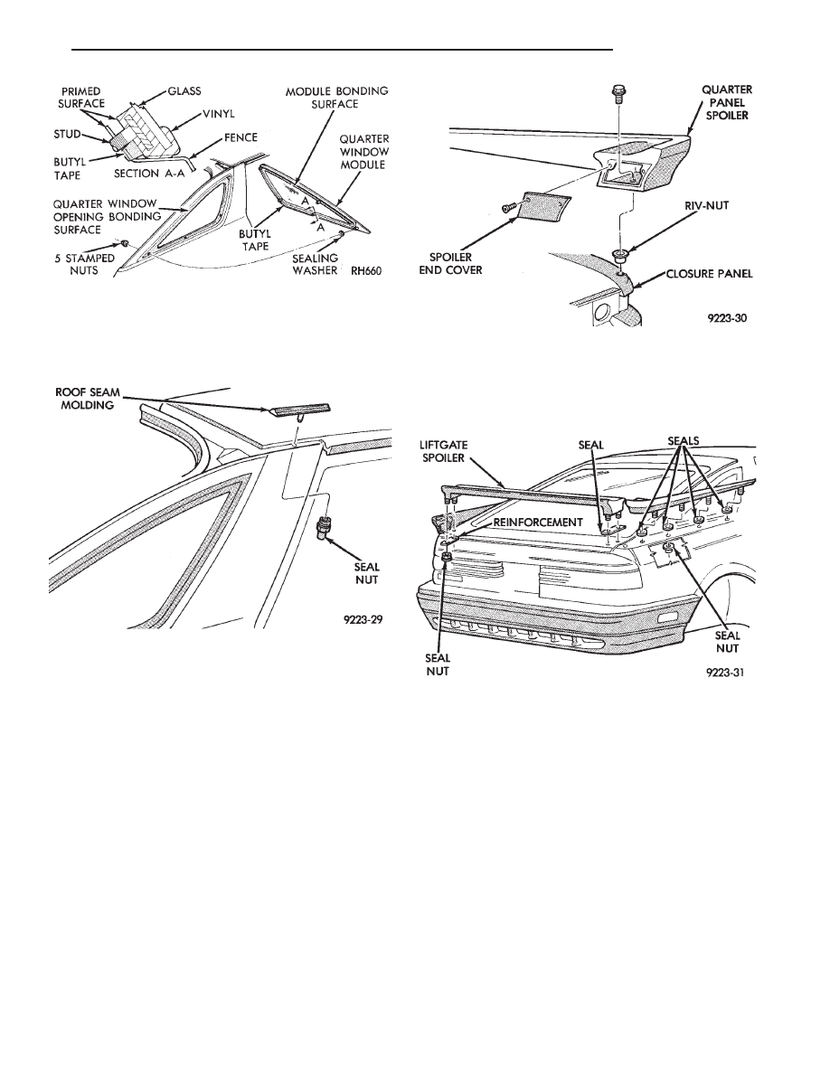
Fig. 36 Quarter Glass Module
Fig. 37 Roof Seam Molding
Fig. 38 Quarter Panel Spoiler
Fig. 39 Lift Gate Spoiler
Ä
AG-BODY
23 - 67
(3) Disconnect lift gate wire connectors and rear
window washer hose, if equipped.
(4) Remove upper lift gate trim molding.
(5) Support lift gate on a suitable lifting device.
(6) Disconnect top of prop cylinders from lift gate.
(7) Mark lift gate hinge locations to assist instal-
lation an alignment of lift gate.
(8) With assistance of a helper, remove bolts hold-
ing lift gate to hinge.
(9) Separate lift gate from vehicle.
INSTALLATION
Reverse the preceding operation.
LIFT GATE LATCH AND STRIKER
LIFT GATE LATCH REMOVAL (FIG. 42)
(1) Raise lift gate to the full open position.
(2) Remove luggage compartment tail trim panel.
(3) Disconnect lock linkage rod from lift gate latch
arm.
(4) Remove nuts holding lift gate latch to tail
panel.
(5) Separate latch from tail panel and disconnect
lift gate remote release cable.
LIFT GATE LATCH INSTALLATION
LIFT GATE STRIKER REMOVAL (FIG. 42)
(1) Raise lift gate to the full open position.
(2) Remove lower lift gate trim panel.
(3) Mark lift gate striker location to assist instal-
lation.
(4) Remove bolts holding lift gate striker to lift
gate.
(5) Separate striker from lift gate.
LIFT GATE STRIKER INSTALLATION
Reverse the preceding operation.
LIFT GATE LOCK CYLINDER
REMOVAL (FIG. 43)
(1) Raise lift gate to the full open position.
(2) Remove luggage compartment tail trim panel.
(3) Disconnect linkage return spring (Fig. 42).
(4) Disconnect linkage rod from lift gate lock arm.
(5) Remove bolts holding lift gate lock to tail
panel.
(6) Separate lock from tail panel.
INSTALLATION
Reverse the preceding operation.
FUEL FILL DOOR
REMOVAL (FIG. 44)
(1) Remove right lower quarter trim panel.
(2) Open fuel fill door.
(3) Remove nuts holding fuel fill door to quarter
panel from in luggage compartment.
(4) Separate fuel fill door from vehicle.
INSTALLATION
Reverse the preceding operation
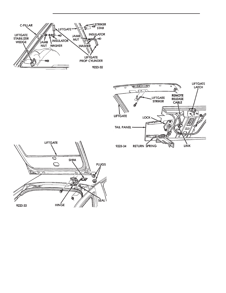
Fig. 40 Lift Gate Prop Cylinder
Fig. 41 Lift Gate
Fig. 42 Lift Gate Latch and Striker
23 - 68
AG-BODY
Ä
LIFT GATE AND FUEL FILL DOOR RELEASE
CABLES
LIFT GATE AND FUEL FILL DOOR CABLES
REMOVAL (FIG. 45)
(1) Remove interior trim as necessary to gain ac-
cess to release cables.
(2) Remove left front door opening scuff plate.
(3) Remove screw holding trim cover to release ca-
ble handle and separate cover from handle.
(4) Remove screw holding release handle to door
sill.
(5) Pry open retainer tab holding cable core end in
handle pivot. Pry cable case end from handle.
(6) On fuel fill door cable, remove nut holding ca-
ble latch to fuel fill opening.
(7) On lift gate latch, remove lift gate latch cover
and disconnect cable end from latch. Route cable
back through trunk lid.
LIFT GATE AND FUEL FILL DOOR CABLES
INSTALLATION
Reverse the preceding operation.
TAIL LAMP CLOSURE PANEL
REMOVAL
(1) Remove lift gate opening scuff plate.
(2) Remove lift gate opening sill cover.
(3) Remove luggage compartment tail panel trim.
(4) Remove lower quarter trim panels.
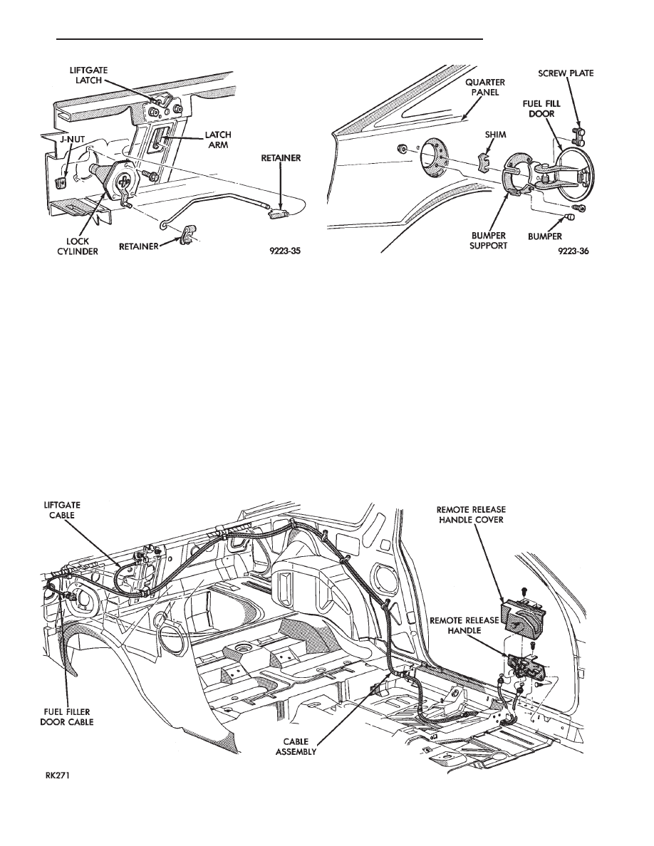
Fig. 45 Lift Gate and Fuel Fill Door Release Cables
Fig. 43 Lift Gate Lock Cylinder
Fig. 44 Fuel Fill Door
Ä
AG-BODY
23 - 69
Нет комментариевНе стесняйтесь поделиться с нами вашим ценным мнением.
Текст