Chrysler Le Baron, Dodge Dynasty, Plymouth Acclaim. Manual — part 163
(5) Remove bolt holding belt retractor to quarter
panel.
(6) Separate belt from vehicle.
OUTBOARD SHOULDER HARNESS/LAP BELT
INSTALLATION
Reverse the preceding operation.
INBOARD BUCKLE REMOVAL (FIG. 26)
(1) Remove bolt holding inboard buckle to floor.
(2) Disconnect seat belt sensor wire connector, if
equipped.
(3) Separate buckle assembly from vehicle.
INBOARD BUCKLE INSTALLATION
Reverse the preceding operation.
REAR SEAT BELTS
REAR OUTBOARD SHOULDER HARNESS/LAP
BELT REMOVAL (FIG. 27)
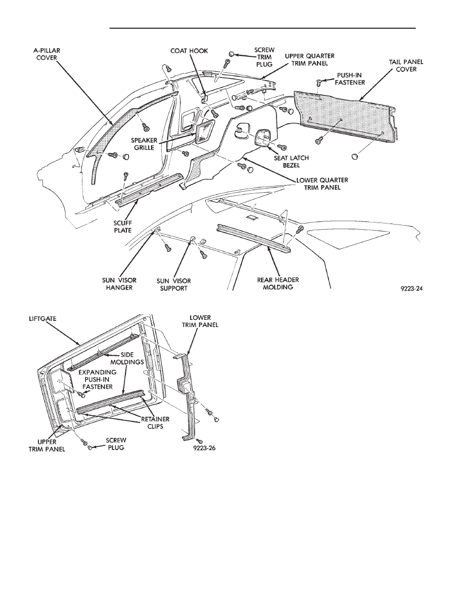
(1) Remove lower and upper quarter trim panel.
(2) Remove bolt holding lap belt anchor to floor at
wheelhouse kickup.
(3) Remove bolt holding seat belt retractor to quar-
ter panel.
REAR OUTBOARD SHOULDER HARNESS/LAP
BELT INSTALLATION
Reverse the preceding operation.
REAR INBOARD BUCKLE REMOVAL (FIG. 27)
(1) Lift seat belt buckle anchor cover to expose
bolt.
(2) Remove bolt holding inboard buckle/center oc-
cupant belt to seat frame.
(3) Separate buckle from vehicle.
Fig. 24 Interior Mouldings, Panels, and Trim Covers
Fig. 25 Lift Gate Trim
23 - 62
AG-BODY
Ä
REAR INBOARD BUCKLE INSTALLATION
Reverse the preceding operation.
FRONT SEATS
REMOVAL (FIG. 28 OR 29)
(1) Position seat full forward.
(2) Remove screws holding rear track riser covers
and separate covers from tracks.
(3) On power seat track, remove outboard track
cover.
(4) Remove nuts holding seat track to floor.
(5) Position seat full rearward.
(6) On power seat track, remove door sill scuff
plate and disconnect wire connector.
(7) Remove bolts holding seat track to cross mem-
ber.
(8) Remove seat from vehicle.
INSTALLATION
Reverse the preceding operation.
REAR SEATS
REMOVAL (FIG. 30)
(1) Hinge seat backs forward.
(2) Remove bolts holding rear seat frame to floor
on sides of center floor hump near luggage compart-
ment kick-up.
(3) Pull seat forward to disengage retaining hooks
from floor.
(4) Separate seat from vehicle.
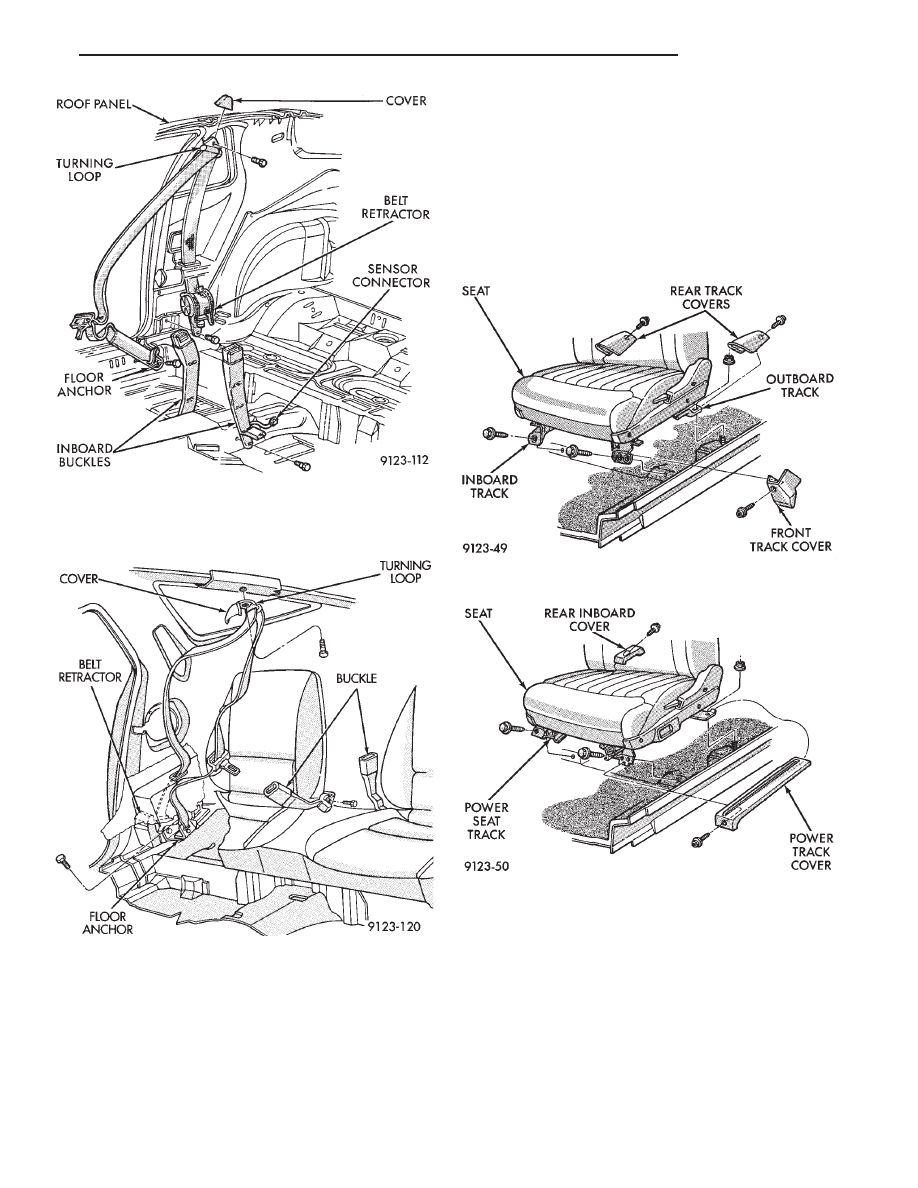
Fig. 26 Front Seat Belts—Typical
Fig. 27 Rear Seat Belts
Fig. 28 Manual Front Seat
Fig. 29 Power Front Seat
Ä
AG-BODY
23 - 63
INSTALLATION
Reverse the preceding operation.
FRONT CENTER CONSOLE
REMOVAL (FIG. 31)
(1) Position front seats full forward.
(2) Remove rear ash tray.
(3) Remove rear lower carpeted end cover.
(4) Remove nuts holding console to floor bracket.
(5) Position front seats full rearward.
(6) Raise console storage bin cover and remove bot-
tom mat.
(7) Remove screws holding bottom of storage bin to
floor bracket.
(8) Remove screws holding console side panels to
instrument panel. Disengage hook and loop fasteners
and separate side panels from console.
(9) Disconnect shift indicator cable and clips from
shift mechanism through right side panel opening, if
equipped with automatic transaxle. Refer to Group
8E, Instrument Panel and Gauges for proper proce-
dures.
(10) Disengage clips holding parking brake lever
cover to console and separate cover from vehicle.
(11) Remove center instrument panel bezel. Refer
to Group 8E, Instrument Panel. Remove screws hold-
ing console to instrument panel.
(12) Remove screws holding console to lower in-
strument panel.
(13) Remove bolts holding console to forward floor
mounting bracket.
(14) Remove gear selector knob.
(15) Separate console from floor and remove from
vehicle.
INSTALLATION
Reverse the preceding operation.
FLOOR CARPET
REMOVAL (FIG. 32)
(1) Remove cowl trim panels and scuff plates.
(2) Remove front seats and inboard seat belts.
(3) Remove center arm rest and front console.
(4) Remove inboard and outboard seat belt lower
attaching bolts.
(5) Remove left dash panel foot rest.
(6) Remove rear seat.
(7) Pull carpet from under quarter trim covers.
(8) Fold carpet and remove through door opening.
INSTALLATION
Reverse the preceding operation.
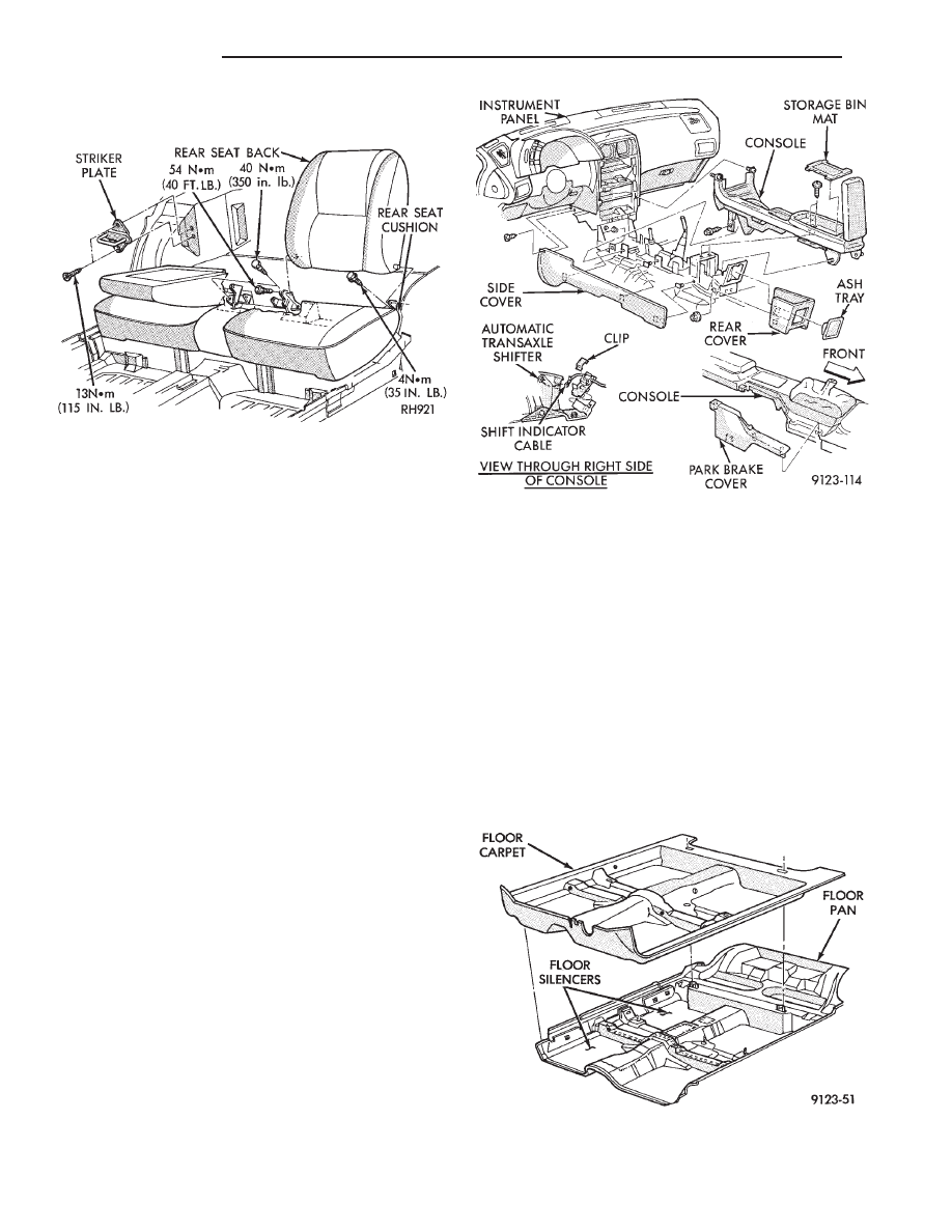
Fig. 30 Rear Seat Cushion and Back
Fig. 31 Center Console
Fig. 32 Floor Carpet and Silencers—Typical
23 - 64
AG-BODY
Ä
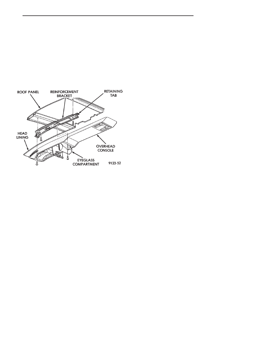
OVERHEAD CONSOLE
REMOVAL (FIG. 33)
(1) Remove screws holding overhead console to re-
inforcement bracket.
(2) Slide overhead console rearward to separate re-
inforcement bracket retainer tab from console.
(3) Lower console from roof and disconnect wire
connectors.
INSTALLATION
Reverse The preceding operation.
HEAD LINING
REMOVAL
(1) Disconnect battery negative cable.
(2) Pull dome lamp downward to disengage from
retaining ring in head lining. Separate lens from
lamp body and remove bulb. Separate bulb holder
from lamp body. Remove attaching screw holding re-
taining ring to roof bow, if equipped.
(3) Remove screws holding coat hooks to roof above
quarter panels.
(4) Remove roof rail and A-pillar mouldings.
(5) Remove screws holding sun visors to roof
header and disconnect wire connector, if equipped.
Remove inboard sun visor hangers.
(6) Remove overhead console, if equipped.
(7) Pull front reading lamp downward to disengage
from retaining ring in head lining and disconnect
wire connector. Remove screws holding retaining
ring to roof header, if equipped.
(8) Remove pinch welt holding headlining to sun
roof opening, if equipped.
(9) Remove screws holding lift gate opening header
moulding to rear roof header. Separate moulding
from header.
(10) Remove one quarter trim panel as necessary
to clear head lining removal path.
(11) Remove head lining from vehicle.
INSTALLATION
Reverse the preceding operation.
SUNROOF LIFT CONTROL
REMOVAL (FIG. 34)
(1) Remove sunroof glass panel. Refer to Owners
manual for proper procedures.
(2) Remove pinch welt holding head lining to edge
of sunroof opening.
(3) Remove trim ring from tilt control handle.
(4) Remove screws holding tilt control handle to
tilt control. Separate handle from control.
(5) Remove nuts holding lift control to roof panel.
Separate lift control from roof.
INSTALLATION
Reverse the preceding operation.
REAR WINDOW GLASS
The rear window moulding often cannot be sal-
vaged after removal operation is completed. Verify
moulding availability from the parts supplier before
removing moulding.
REMOVAL (FIG. 35)
(1) Remove rear window moulding.
(2) Remove lift gate trim as necessary to gain ac-
cess to rear window defogger wire connector and
ground screw, if equipped.
WARNING: WEAR EYE AND HAND PROTECTION
WHEN HANDLING SAFETY GLASS. PERSONAL IN-
JURY CAN RESULT.
CAUTION: Do not damage body or trim finish when
cutting out glass or applying fence primer.
(3) Cut the urethane around the perimeter of the
back window glass. Refer to Windshield section of
this group for proper procedures.
(4) Separate the rear window from the vehicle.
INSTALLATION
(1) Prepare the work area, window fence, and glass
the same way as described in the Windshield section
of this group.
(2) Place the fence spacers at the locations shown
(Fig. 35).
(3) Apply a 10 mm (0.4 in.) bead of urethane
around the perimeter of the glass.
(4) Install the glass in the same manner described
in the Windshield section of this group.
(5) Install the rear window moulding. Apply 50
mm (2 in.) masking tape over moulding to assure
alignment.
(6) Connect rear window defogger wiring and in-
stall lift gate trim.
Fig. 33 Overhead Console—Typical
Ä
AG-BODY
23 - 65
Нет комментариевНе стесняйтесь поделиться с нами вашим ценным мнением.
Текст