Chrysler Le Baron, Dodge Dynasty, Plymouth Acclaim. Manual — part 312
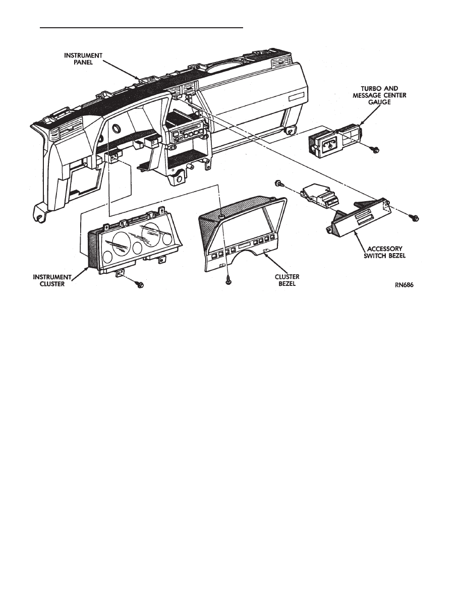
CLUSTER BEZEL REPLACEMENT
(1) Remove four screws holding bezel to instru-
ment panel (Fig. 7).
(2) Remove bezel over steering wheel.
(3) For installation reverse above procedures.
CLUSTER MASK AND LENS
REMOVAL
(1) Remove instrument cluster bezel.
(2) Remove five screws holding mask and lens to
cluster.
(3) Remove mask and lens.
(4) For installation reverse above procedures.
CLUSTER ASSEMBLY REPLACEMENT
(1) Disconnect battery to assure no Air Bag Sys-
tem fault codes are stored.
(2) Remove cluster bezel (Fig. 7).
(3) Remove the upper steering column cover.
(4) Remove the four screws attaching cluster hous-
ing to the base panel.
(5) Pull cluster rearward, reach behind cluster and
disconnect the two wiring harnesses.
(6) Remove cluster assembly.
INSTALLATION
(1) Connect wiring harnesses.
(2) Position cluster and secure to base panel with
four screws.
(3) Install upper and lower steering column cover.
(4) Install cluster bezel.
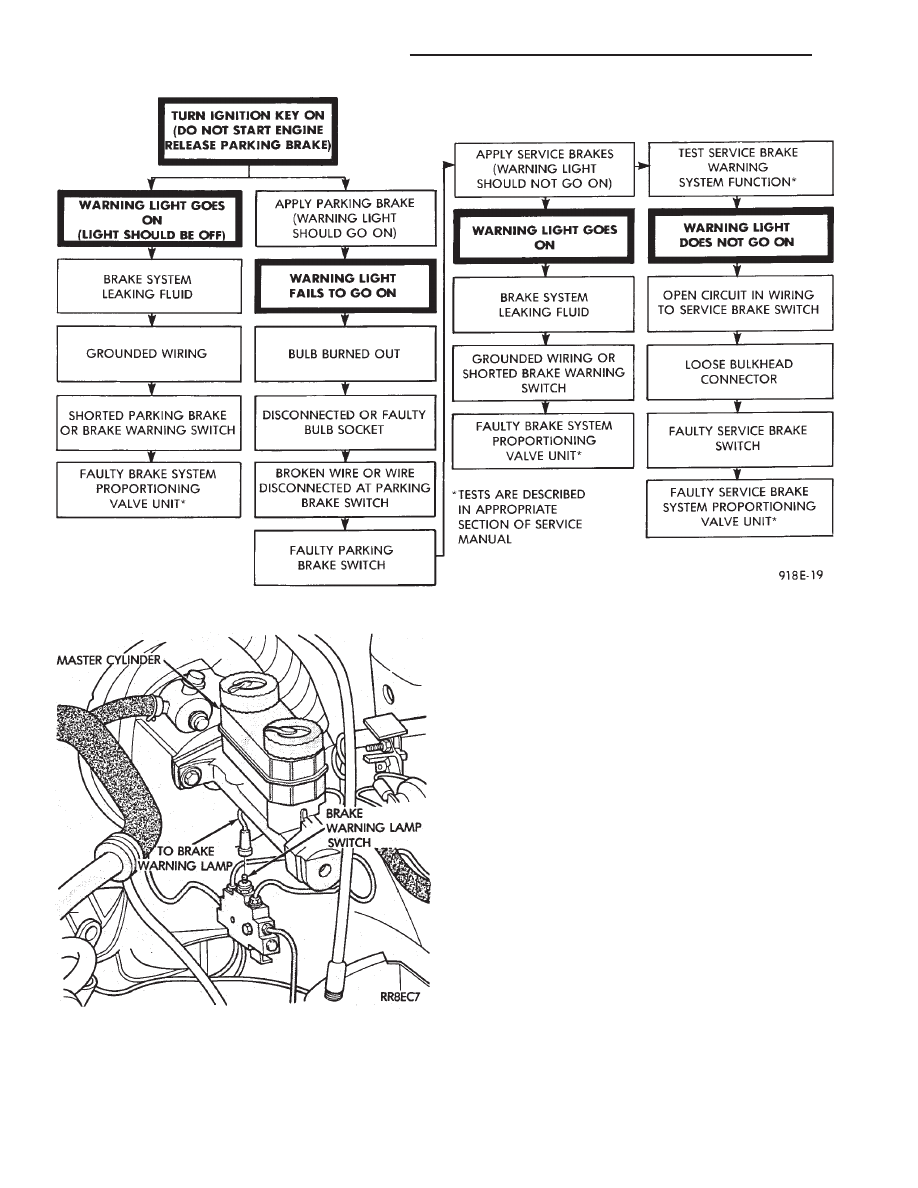
Fig. 5 Brake System Warning Lamp Diagnosis
Fig. 6 Brake Warning Lamp Switch
8E - 60
INSTRUMENT PANEL AND GAUGES
Ä
(5) Reconnect battery.
GAUGES
CAUTION:
During
the
removal
and
installation
watch overlays are not damage.
It is not necessary to remove instrument cluster
from vehicle for gauge replacement.
When removing gauge assemblies from cluster,
gauge must be pulled straight out, not twisted, or
damage to gauge pins may result.
MULTIPLE GAUGE INOPERATIVE
Volt, speedometer, tachometer and other gauges
appear to malfunction. Also check warning indicator
lamps:
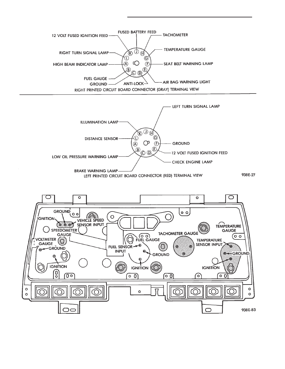
(1) Remove cluster
(2) Check for ignition voltage at pin E of the red
connector. If no voltage, repair as necessary (Fig. 8).
(3) Check for ground continuity between pin C of
the gray connector. If no ground, repair as necessary.
(4) If voltage and ground OK and pins or connec-
tors are not distorted, replace printed circuit board.
(5) Install cluster.
SINGLE GAUGE INOPERATIVE (FIG. 9 AND
10)
(1) Remove gauge in question.
(2) With the ignition key ON, check for ignition
voltage at ignition pin of gauge. Check for ground at
ground pin of gauge.
(a) If no voltage or ground, remove cluster and
check pin E red connector for ignition voltage or
pin C gray connector for ground (Fig. 8).
(b) If no voltage or ground, repair as necessary.
Refer to 8W, Wiring Diagrams.
(c) If there is voltage or ground, check cluster for
distorted terminals. If terminals are OK, replace
printed circuit board.
(3) When testing the temperature gauge, allow the
engine to run until the vehicle reaches a normal op-
erating temperature. Turn ignition OFF and remove
gauge from cluster.
• When checking the temperature and oil pressure
gauges, it is important to have the same engine tem-
perature and engine speed when noting gauge posi-
tion.
• The time between gauge position reading and
sending unit measuring should be kept to a mini-
mum.
• When testing oil pressure gauge, engine needs to
be running.
(a) Measure and record the resistance between
sending unit pin and ground pin of the gauge in
question. Refer to Gauge Calibration.
Fig. 7 Upper Instrument Panel Components
Ä
INSTRUMENT PANEL AND GAUGES
8E - 61
(b) If resistance and gauge position are not sim-
ilar, replace gauge.
(c) If OK, test resistance from the sending unit
to the cluster connector.
(d) If reading is different from the first resis-
tance measured, check printed circuit board for
contact to cluster connector.
(e) If OK and contacts are not distorted, replace
printed circuit board.
Fig. 8 Printed Circuit Board Connector
Fig. 9 Instrument Cluster With Tachometer
8E - 62
INSTRUMENT PANEL AND GAUGES
Ä

(f) If everything checks out OK, refer to Sending
Unit Test.
(4) With the ignition switch in the ON position,
check for battery voltage across the ignition pin and
the ground pin.
(5) If fuel gauge meets specifications check fuel
tank and original fuel tank sending unit as follows:
(a) Carefully remove fuel tank sending unit from
tank.
(b) Refer to sending unit removal Group 14,
Fuel.
(c) Connect sending unit wire and jumper wire
as described in the test procedure.
(6) If fuel gauge now checks within specifications,
original sending unit is electrically okay, check fol-
lowing as a possible cause:
(a) Ground wire from sending unit to left side
cowl for continuity.
(b) Sending unit deformed. Make sure sending
unit float arm moves freely and pick up tube is not
bent upwards creating an interference with bottom
of tank and inspect float.
(c) Sending unit improperly installed. Install
properly.
(d) Mounting flange on fuel tank for sending
unit deformed. Feel for interference fit of sending
unit to bottom of tank. It is permissible to bend
pick up tube down a little near mounting flange to
gain interference fit.
(e) Fuel tank bottom deformed, causing improper
positioning of sending unit pick up tube. Replace or
repair tank and recheck sending unit.
GAUGE CALIBRATION
(1) Remove the gauge.
(2) Check for ignition voltage and ground to the
gauge.
(3) With the ignition key in the OFF position, re-
place gauge. Turn the ignition key to the ON posi-
tion. To test oil pressure gauge engine must be
running. When testing oil or temperature gauge the
engine should be at normal operating temperature.
Record the gauge position.
(4) Remove gauge and record the resistance be-
tween the sending unit pin and the gauge ground
pin. When checking gauges, it is important to have
the same engine temperature and speed when noting
gauge position. The time between gauge reading and
measuring should be kept to a minimum.
(5) Resistance Chart (Fig. 11), is general guide-
lines for checking the gauge position against the
sending unit resistance.
Because of only a few specific points of gauge posi-
tion versus sending unit resistance, a good estimate
is needed when the resistance falls between gradua-
tions. Even when the resistance corresponds to grad-
uations, the gauge has a tolerance of
6 4 ohms.
Volt gauge: The calibration dot on the volt gauge
corresponds to 13 volts between the gauge ignition
and ground pins. If voltage varies from this, estimate
proper gauge position with input voltage.
FUEL GAUGE REPLACEMENT
(1) Remove instrument cluster bezel.
(2) Remove mask and lens.
(3) If equipped with tachometer, remove three re-
taining screws and pull the tach straight back.
Fig. 10 Instrument Cluster Without Tachometer
Ä
INSTRUMENT PANEL AND GAUGES
8E - 63
Нет комментариевНе стесняйтесь поделиться с нами вашим ценным мнением.
Текст