Chrysler Le Baron, Dodge Dynasty, Plymouth Acclaim. Manual — part 313
(4) Remove two retaining screws and pull fuel
gauge straight back.
(5) For installation reverse above procedures.
TEMPERATURE GAUGE REPLACEMENT
(1) Remove instrument cluster bezel (Fig. 7).
(2) Remove mask and lens.
(3) Remove two retaining screws and pull temper-
ature gauge straight back.
(4) For installation reverse above procedures.
VOLTMETER REPLACEMENT
(1) Remove instrument cluster bezel (Fig. 7).
(2) Remove mask and lens.
(3) Remove three speedometer retaining screws
and pull the speedometer straight back and set aside.
(4) Remove two voltmeter retaining screws and
pull voltmeter straight back.
(5) For installation, place voltmeter on gauge pins
and push until gauge is securely seated in cluster
and reverse above procedures.
TACHOMETER REPLACEMENT
(1) Remove instrument cluster bezel.
(2) Remove mask and lens.
(3) Remove three retaining screws and pull ta-
chometer straight back.
(4) For installation, place tachometer on gauge
pins and push until gauge is securely seated in clus-
ter and reverse above procedures.
TACHOMETER CIRCUIT TESTING
(1) Remove cluster.
(2) Check for battery voltage at cavity J if instru-
ment cluster gray connector.
(3) With the ignition in the ON position, check for
battery voltage at cavity K of the instrument cluster
gray connector (Fig. 8).
(4) Check cavity F of the instrument cluster red
connector for continuity to ground (Fig. 8).
(5) Check for tachometer signal from the power-
train control module by connecting an AC DIGITAL
VOLTMETER to cavity H of the instrument cluster
gray connector and ground. A reading of at least 1.0
volts should be present with the engine running.
(a) If voltage is within specification, go to step 7.
(b) If voltage is NOT within specification, per-
form steps 5 and 6.
(6) If there is less than 1.0 volts at cavity H check
for continuity between cavity H of the instrument
cluster and pin 43 of the powertrain control module
connector (Fig. 12). Also, check the connector at the
powertrain control module for damaged pins or ter-
minal push outs.
(7) If voltage is less than 1.0 volts at cavity H and
there is continuity between cavity H of the instru-
Fig. 11 Gauge Resistance
8E - 64
INSTRUMENT PANEL AND GAUGES
Ä

ment cluster and pin 43 of the powertrain control
module connector, replace the powertrain control
module.
(8) If all tests performed test good replace the ta-
chometer drive module.
(9) If the tachometer continues to be inoperative,
replace the tachometer assembly.
TACHOMETER DRIVE MODULE
REPLACEMENT
(1) Remove instrument cluster (Fig. 13).
(2) Remove drive module by pivoting upward from
printed circuit board and pulling away from locating
notches.
(3) For installation, position module on locating
notches and push down securely over printed circuit
board and reverse above procedures.
SPEEDOMETER SYSTEM
AP-body vehicles are equipped with electronically
driven speedometer and odometer assemblies. The
unit has the same appearance as a conventional
speedometer but it eliminates the cable-driven me-
chanical system. A signal is sent from a transmis-
sion-mounted
speed
sensor
to
the
speedometer
circuitry through the wiring harness. By eliminating
the speedometer cable, instrument cluster service
and removal is improved. Refer to Fig. 14 Speedom-
eter Diagnosis.
When the speedometer is out of calibration. The
electronic automatic transaxle vehicle speed sensor
output must be calibrated to reflect the different
combinations of equipment. The procedure is called
Pinion Factor, refer to Group 21, Transaxle for the
procedure.
SPEEDOMETER/ODOMETER ASSEMBLY
REPLACEMENT
(1) Remove cluster bezel.
(2) Remove cluster mask and lens.
(3) Remove tachometer. If equipped.
(4) Remove fuel gauge.
(5) Remove three screws attaching speedometer/
odometer assembly to the cluster housing.
(6) Pull speedometer rearward to remove from
cluster housing.
(7) For installation reverse above procedures.
VEHICLE SPEED SENSOR REPLACEMENT
(1) Remove harness connector from sensor and
make sure weather seal is on harness connector.
(2) Remove sensor retaining bolt.
(3) Pull sensor and pinion gear assembly out of
transaxle. If necessary, carefully pry loose with a flat
blade screwdriver (Fig. 15 and 16).
(4) For installation reverse above procedures and
seat sensor assembly by hand to insure proper gear
engagement. Tighten retaining bolt to 7 N
Im (60 in.
lbs.) torque.
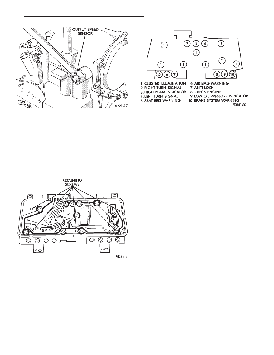
ELECTRONIC AUTOMATIC TRANSAXLE
VEHICLE SPEED SENSOR REPLACEMENT
The output vehicle speed sensor is located to the
left of the manual shift lever.
(1) Raise and support vehicle on safety stands.
(2) Remove vehicle speed sensor (Fig. 17).
(3) For installation, reverse above procedures.
Fig. 12 Powertrain Control Module Pin Location
Fig. 13 Tachometer Drive Module
Ä
INSTRUMENT PANEL AND GAUGES
8E - 65
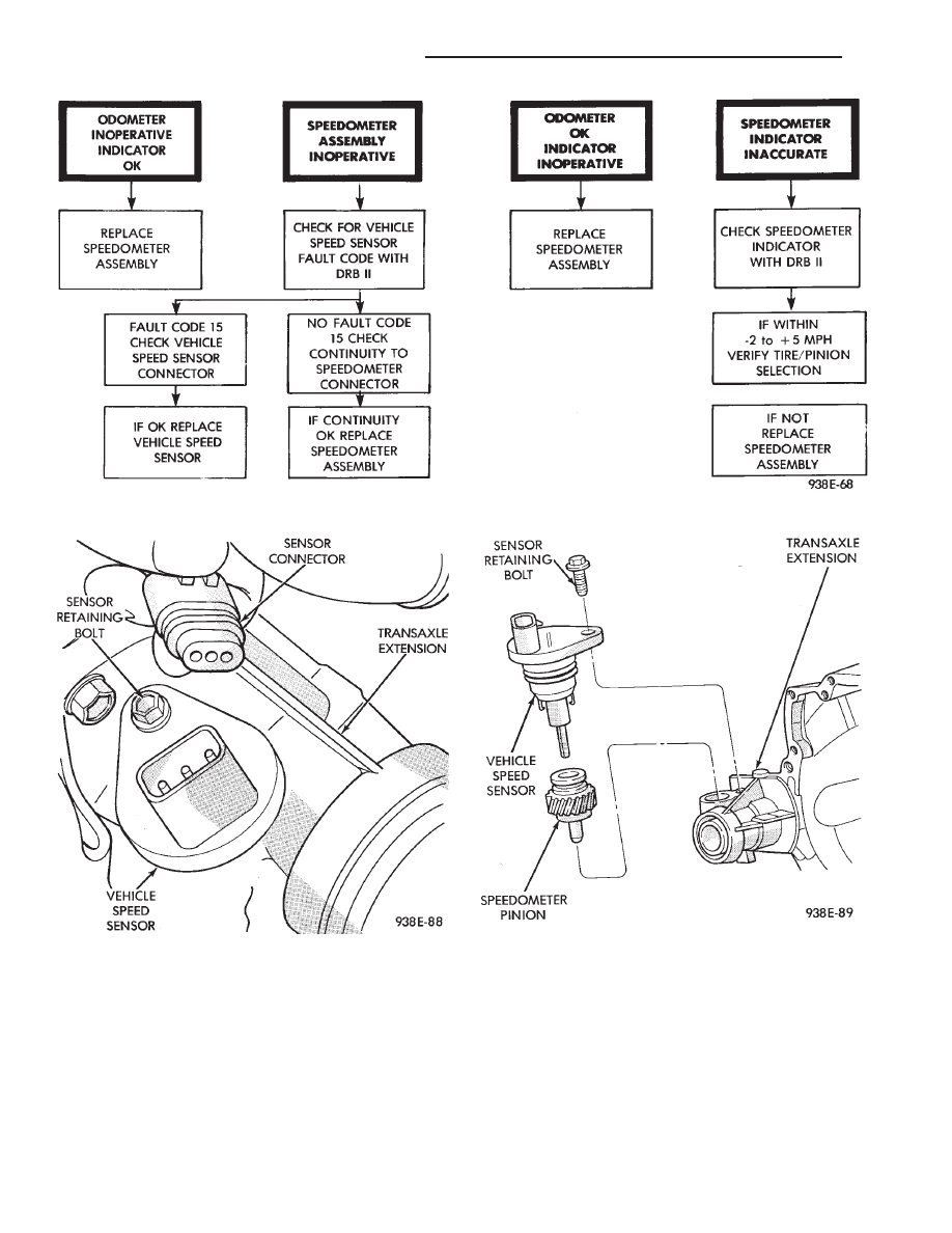
Fig. 14 Speedometer System Diagnosis
Fig. 15 Vehicle Speed Sensor and Connector
Fig. 16 Vehicle Speed Sensor and Speedometer
Pinion
8E - 66
INSTRUMENT PANEL AND GAUGES
Ä
VEHICLE SPEED SENSOR TEST
For testing of the vehicle speed sensor and related
components using DRB II, refer to the appropriate
Powertrain Diagnostics Test Procedure Manual.
PRINTED CIRCUIT BOARD REPLACEMENT
(1) Remove cluster bezel.
(2) Remove instrument cluster.
(3) Remove tachometer drive module, if equipped.
(4) Remove six retaining screws (Fig. 18).
(5) Twist out all illumination and warning lamp
sockets.
(6) Pull printed circuit board from cluster housing.
(7) For installation reverse above procedures. Posi-
tion printed circuit board on cluster housing, being
certain that all gauge pins are inserted correctly.
CLUSTER LAMP REPLACEMENT
Illumination Lamp Chart shows cluster as viewed
from rear. However, all lamps must be replaced by
removing cluster from instrument panel (Fig. 19).
SWITCH AND PANEL COMPONENT SERVICE
LOWER STEERING COLUMN COVER
REPLACEMENT
(1) Disconnect park brake release rod from the
park brake handle.
(2) Remove two screws attaching hood release (Fig.
20).
(3) Remove fuse access door and remove steering
column cover attaching screw located directly above
the fuse block.
(4) Remove six screws around outside of steering
column cover.
(5) Remove steering column cover.
(6) For installation reverse above procedures.
CENTER MODULE LOWER COVER
REPLACEMENT
(1) Open ash receiver and remove center module
bezel.
(2) Remove module cover to instrument panel re-
taining screws (Fig. 20).
(3) Remove module cover from vehicle.
(4) For installation reverse above procedures.
CENTER MODULE BEZEL REPLACEMENT
(1) Open ash receiver.
(2) Grip module bezel around outer edges and pull
rearward to release six spring-type retaining clips
(Fig. 20).
(3) For installation position spring clips to instru-
ment panel and push firmly until seated.
(4) Close ash receiver.
Fig. 17 Vehicle Speed Sensor Removal
Fig. 18 Printed Circuit Board
Fig. 19 Instrument Cluster Illumination Lamps
Ä
INSTRUMENT PANEL AND GAUGES
8E - 67
Нет комментариевНе стесняйтесь поделиться с нами вашим ценным мнением.
Текст