Chrysler Le Baron, Dodge Dynasty, Plymouth Acclaim. Manual — part 226
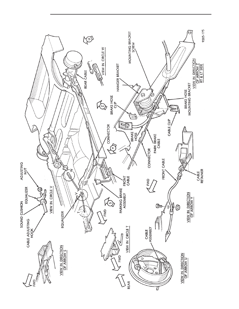
FIG.
2
PARKING
BRAKE
CABLE
ROUTING
AA
AND
AP
BODY
5 - 58
BRAKES
Ä
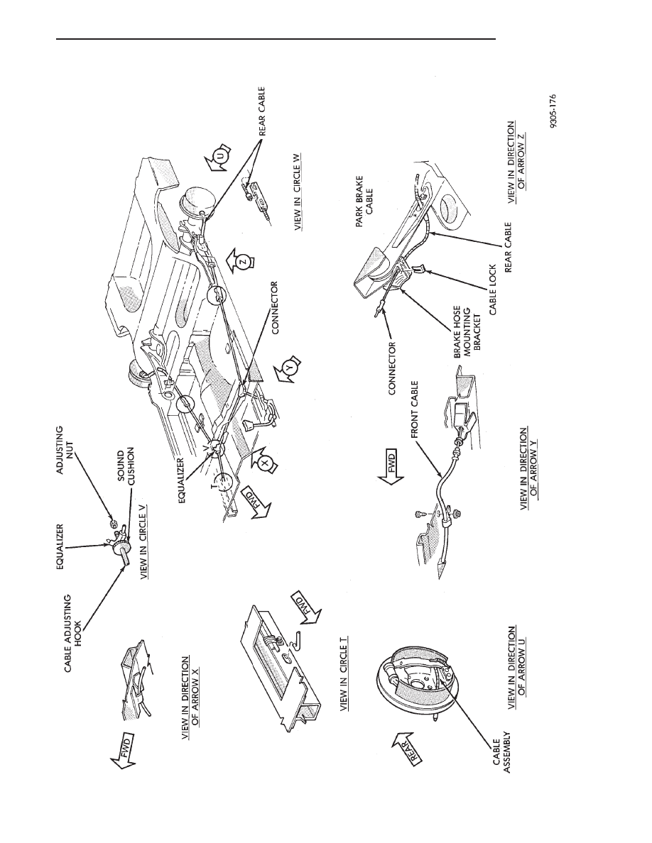
FIG.
3
PARKING
BRAKE
CABLE
ROUTING
AC
AND
A
Y
-BODY
Ä
BRAKES
5 - 59
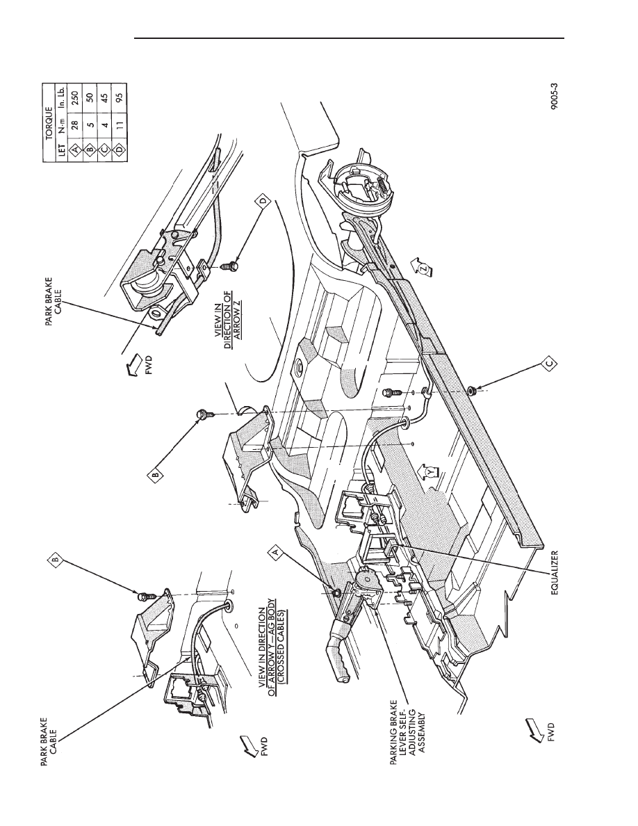
FIG.
4
PARKING
BRAKE
CABLE
ROUTING
AG
AND
AJ
BODY
5 - 60
BRAKES
Ä
WARNING: THE SELF ADJUSTING FEATURE OF THIS
PARKING BRAKE LEVER ASSEMBLY CONTAINS A
CLOCK SPRING LOADED TO APPROXIMATELY 30
POUNDS. CARE MUST BE TAKEN TO PREVENT EX-
CESSIVE JARRING OF THE ASSEMBLY. DO NOT
RELEASE THE SELF ADJUSTER LOCKOUT DEVICE
BEFORE INSTALLING CABLES INTO THE EQUAL-
IZER. KEEP HANDS OUT OF SELF ADJUSTER SEC-
TOR AND PAWL AREA. FAILURE TO OBSERVE CAU-
TION IN HANDLING THIS MECHANISM COULD LEAD
TO SERIOUS INJURY.
When repairs to the hand lever assembly or cable
system are required the self adjuster must be reloaded
and locked out.
SELF ADJUSTING PROCEDURES (AG & AJ BODY)
TO RELOAD SELF ADJUSTER
(1) Remove ash receiver or courtesy light from rear
of center console to gain access to self adjuster. Also,
remove carpet from sides of console.
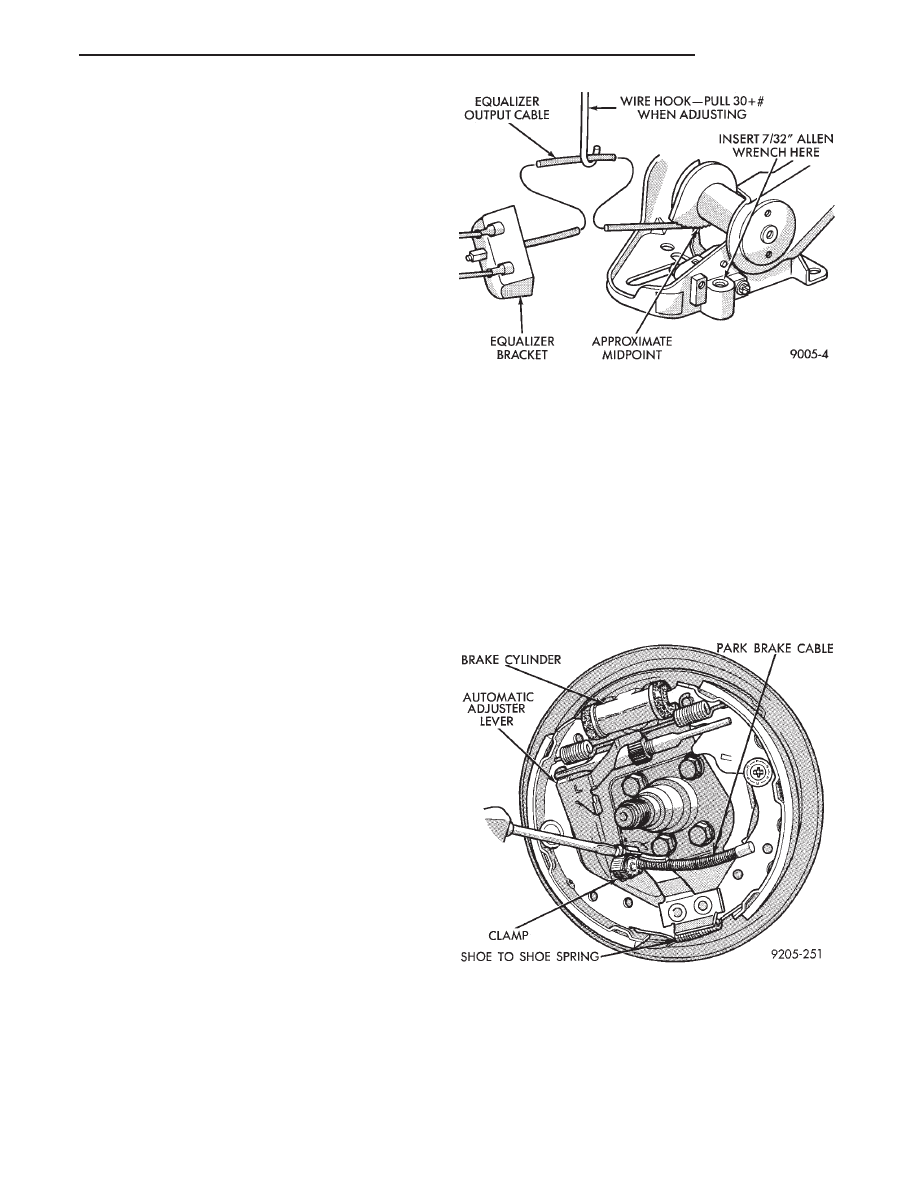
(2) Pull on equalizer/output cable to wind up sprin-
g(requires greater than 30 pounds effort). Continue
until self adjuster lockout pawl is positioned about
midway on the self adjuster sector (Fig. 6). Rotate
lockout pawl into self adjuster sector by turning allen
screw clockwise. Rotating lockout device requires
very little effort. Do not force or failure of lock-
out device will occur.
(3) When repairs are complete, adjust rear brakes
before adjusting parking brake. On drum-in-hat type of
rear disc brake adjust shoe diameter to 171.5 mm (6.75
inch).
ADJUST PARKING BRAKE (AG & AJ BODY)
Be sure that the cables are properly assembled to the
equalizer bracket prior to cable adjustment.
(1) Insert a 7/32 inch allen wrench into hex socket
and turn counter-clockwise through approximately 15°
of rotation (Fig. 4). In turning lockout device, self
adjuster release is a loud snapping noise followed by
reaching a more felt than heard detent. Very light
effort is required to seat lockout arm into detent.
Follow through to the detent is important in prevent-
ing the lockout rod from rattling.
Note: The parking brake handle can be in any
position when releasing self adjuster.
(2) Cycle lever to position cables. Rear wheels should
rotate freely without dragging.
REAR PARKING BRAKE CABLE REMOVAL (AA, AC,
AP, AY BODY)
The rear brake cables are attached to rear connec-
tors.
Should it become necessary to remove either parking
brake cable for installation of a new cable, proceed as
follows:
With vehicle jacked up on a suitable hoist, remove
wheel and tire assembly (Fig. 6).
Back off cable adjusting nut to provide slack and
disconnect rear brake cable from connector.
DRUM BRAKES
(1) Disconnect park brake cable from park brake
lever in rear wheel brakes.
(2) Using an aircraft type hose clamp compress re-
tainers on end of cable housing and start cable out of
retaining hole in the support plate. Remove clamp
when retainers are free of the mounting hole in the
support plate, (Fig. 6).
(3) Remove clip from brake cable at support
bracket and pull cable away from trailing arm as-
sembly (Figs. 3 and 4).
DISC BRAKES
(1) Remove disc brake caliper from adapter, and
brake disc (rotor) from rear hub.
Fig. 5 Self Adjusting Parking Brake Lever Assembly
Fig. 6 Removing Brake Cable from Support Plate
Ä
BRAKES
5 - 61
Нет комментариевНе стесняйтесь поделиться с нами вашим ценным мнением.
Текст