Chrysler Le Baron, Dodge Dynasty, Plymouth Acclaim. Manual — part 225
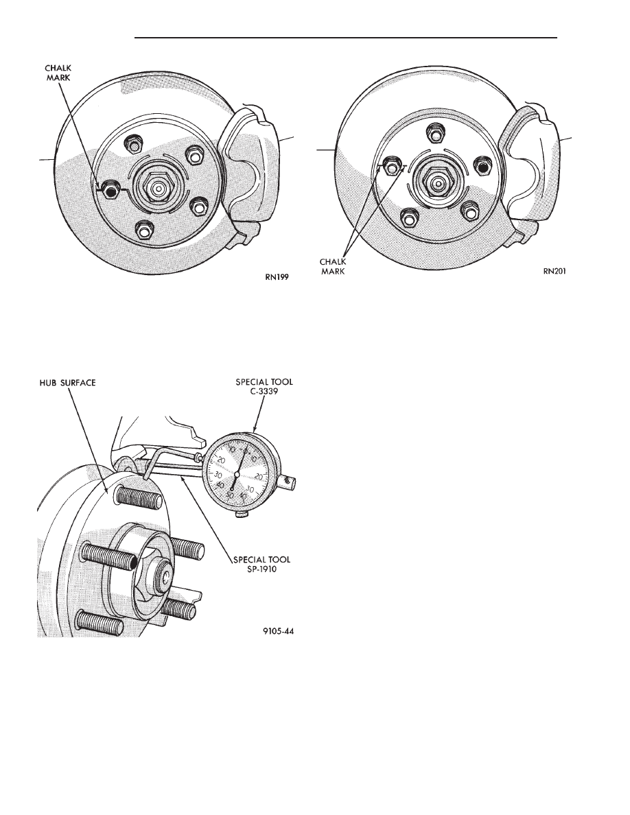
knuckle. Position stem so it contacts hub face near
outer diameter. Care must be taken to position stem
outside the stud circle but inside the chamfer on the
hub rim. Clean hub surface before checking. (See
Fig. 3)
Runout should not exceed 0.08 mm (0.003 inch). If
runout exceeds this specification, hub must be re-
placed. See Suspension Group 2. If hub runout does
not exceed this specification, install disc on hub with
chalk marks two wheel studs apart (Fig. 4). Tighten
nuts in the proper sequence and torque to specifica-
tions. Finally, check runout of disc to see if runout is
now within specifications.
If runout is not within specifications. Install a new
braking disc or reface disc, being careful to remove
as little as possible from each side of disc. Remove
equal amounts from each side of disc. Do not reduce
thickness below minimum thickness cast into the un-
machined surface of the rotor.
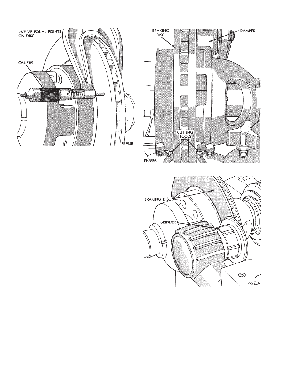
Thickness variation measurements of disc should
be made in conjunction with runout. Measure thick-
ness of disc at 12 equal points with a micrometer at
a radius approximately 25.4 mm (1 inch) from edge
of disc (Fig. 5). If thickness measurements vary by
more than 0.013 mm (0.0005 inch) disc should be re-
moved and resurfaced (Figs. 6 and 7), or a new disc
installed. If cracks or burned spots are evident in the
disc, disc must be replaced.
Light scoring and/or wear is acceptable. If heavy
scoring or warping is evident, the disc must be refin-
ished or replaced (See Refinishing/Refacing Braking
Disc). If cracks are evident in the disc, replace the
disc.
BRAKING DISC REMOVAL
(1) Raise vehicle on hoist or jackstands. Remove
wheel and tire assembly.
(2) Remove caliper assembly, as described under
Brake Shoe Removal in this Group, (but do not dis-
connect brake line). Suspend caliper from wire hook
or loop to avoid strain on flexible hose.
(3) Remove braking disc from the hub.
INSTALLING BRAKING DISC
(1) Slide braking disc on hub. Clean both sides of
braking disc with alcohol or suitable solvent.
(2) Install caliper assembly, as described in Brake
Shoe Installation paragraph.
Fig. 2 Marking Braking Disc and Wheel Stud
Fig. 3 Checking Hub for Runout
Fig. 4 Index Braking Disc and Wheel Stud
5 - 54
BRAKES
Ä
REFINISHING BRAKING DISC
REFACING BRAKING DISC
Refacing of the braking disc is not required each
time the shoe assemblies are replaced.
If the braking disc surface is deeply scored or
warped or there is a complaint of brake roughness or
pulsation the rotor should be resurfaced or refaced
(Figs. 6 and 7).
When refacing a braking disc the required 0.10
mm (0.004 inch) TIR (Total Indicator Reading) and
0.013 mm (0.0005 inch) thickness variation limits
MUST BE MAINTAINED. Extreme care in the op-
eration of braking disc turning equipment is re-
quired.
The collets, shafts and adapters used on the brake
lathe and the bearing cups in the rotor MUST be
clean and free from any chips or contamination.
When mounting the disc on the brake lathe, strict
attention to the brake lathe manufacturer’s operat-
ing instructions is required.
If the disc is not mounted properly the run-out will
be worse after refacing than before refacing.
The use of a double straddle cutter (Fig. 6) that
machines both sides of the disc at the same time is
highly recommended.
RESURFACING BRAKING DISC
This operation can be used when disc surface is
rusty, has lining deposits or excessive runout or
thickness variation is evident.
A sanding disc attachment will remove surface con-
tamination without removing much braking disc ma-
terial.
It will generally follow variations in thickness that
are in the disc.
The following chart shows the location of measure-
ments and specifications when servicing the braking
disc.
All braking discs have markings for minimum
allowable thickness cast on an un-machined sur-
face of the braking disc (Fig. 8). The thickness
Fig. 5 Checking Disc for Thickness
Fig. 6 Refacing Braking Disc
Fig. 7 Resurfacing Braking Disc (Final Finish)
Ä
BRAKES
5 - 55
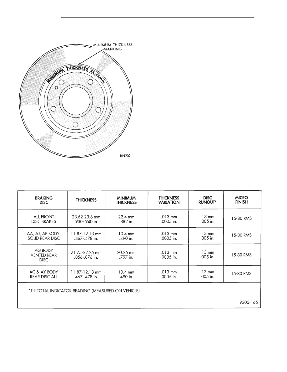
markings may be located on the disc as shown
in (Fig. 8) or on an alternate surface.
This marking includes 0.76 mm (0.030 inch) allow-
able
disc
wear
beyond
the
recommended
0.76
mm(0.030 inch) of disc refacing.
Fig. 8 Minimum Thickness Markings
BRAKING DISC (ROTOR) REFINISHING LIMITS
5 - 56
BRAKES
Ä
PARKING BRAKES
INDEX
page
page
Adjust Parking Brake (AG & AJ Body)
. . . . . . . . 61
General Information
. . . . . . . . . . . . . . . . . . . . . . . 57
Installing Parking Brake Front Cable (AA, AC, AP
AY Body)
. . . . . . . . . . . . . . . . . . . . . . . . . . . . . 62
Installing Parking Brake Shoes
. . . . . . . . . . . . . . 64
Parking Brake Hand Lever Assembly Removal and
Installation
. . . . . . . . . . . . . . . . . . . . . . . . . . . . 63
Rear Parking Brake Cable Installation
. . . . . . . . . 62
Rear Parking Brake Cable Removal (AA, AC, AP,
AY Body)
. . . . . . . . . . . . . . . . . . . . . . . . . . . . . 61
Removal and Installation Parking Brake Shoes
. . 63
Removing Parking Brake Front Cable (AA, AC, AP,
AY Body)
. . . . . . . . . . . . . . . . . . . . . . . . . . . . . 62
Self Adjusting Procedures (AG & AJ Body)
. . . . . 61
Service Procedures
. . . . . . . . . . . . . . . . . . . . . . . 57
GENERAL INFORMATION
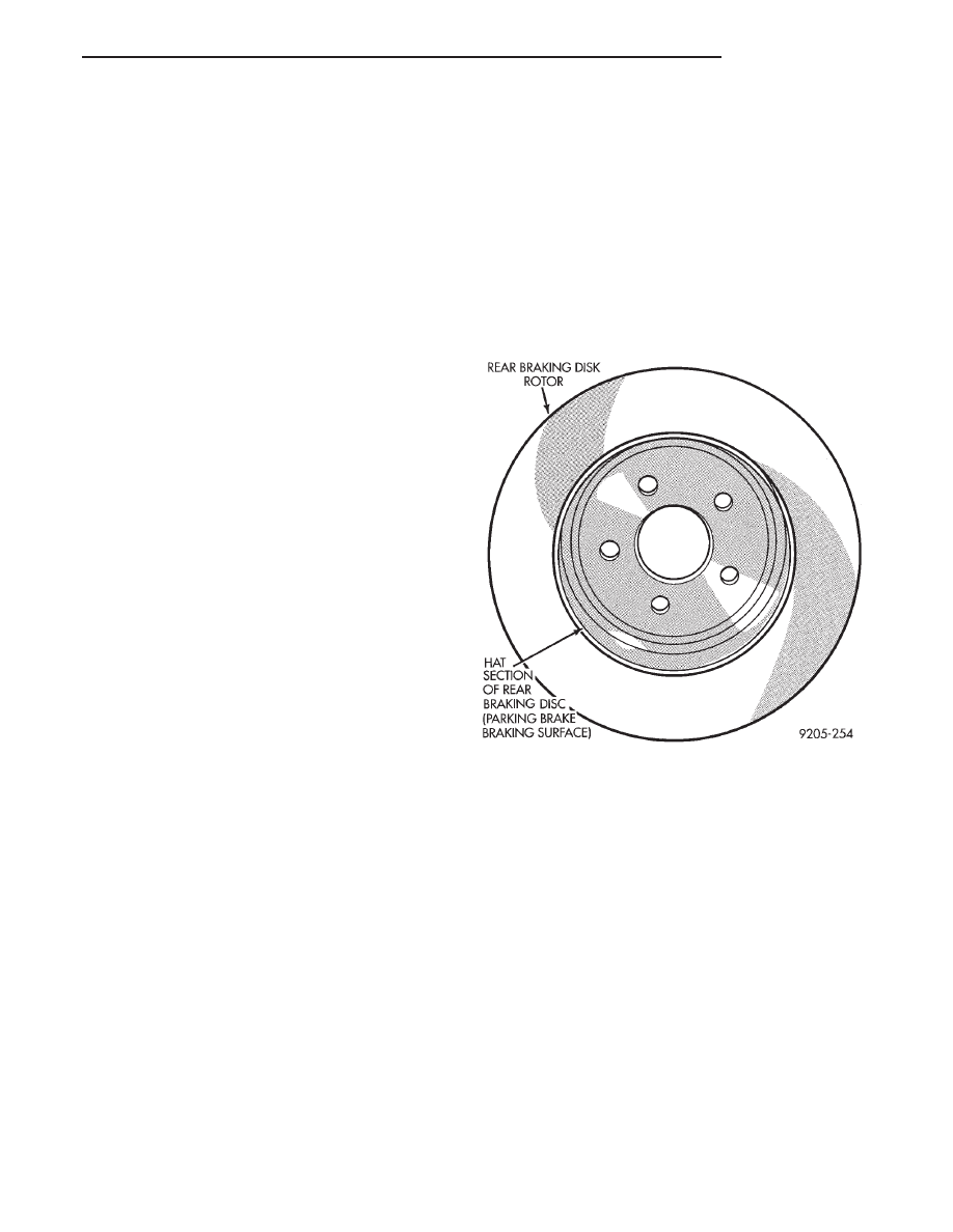
The parking brake mechanism on vehicles with
rear disc brake applications. Consists of a small duo-
servo brake which is mounted to the adapter. The
hat (center) section (Fig. 1) of the rear rotor serves as
the braking surface (drum) for the parking brakes.
On AA, AC, AP, AY body vehicles with rear disc
brake applications, the parking brake cable system is
similar in design to the drum brake parking brake
system.
The parking brake system on the AG and AJ body
vehicles is a 2 cable design. One individual park
brake cable operates each rear park brake mecha-
nism, and brake application is balanced by an equal-
izer at the park brake lever.
On rear drum brake applications, the rear wheel
service brakes also act as parking brakes. The rear
drum brake shoes are mechanically operated by an
internal lever and strut connected to a flexible steel
cable. The wheel brake cables are joined to an inter-
mediate cable which attaches to the front cable lead-
ing to the foot lever (Figs. 2, 3 and 4).
SERVICE PROCEDURES
ADJUSTING PARKING BRAKE
AP, AA, AC & AY (WITH FOOT LEVER)
The service brakes must be properly adjusted be-
fore adjusting the parking brake.
Release the parking brake lever then back-off
parking brake cable adjustment so there is slack in
the cable (Figs. 2 and 3).
Before loosening cable adjusting nut, clean threads
with a wire brush, and lubricate with Mopar Multi-
Purpose grease on equivalent.
The rear brakes adjust every time you depress the
brake pedal.
Adjust the parking brake after service brake ad-
justment by tightening the adjusting nut until a
slight drag is felt while rotating the wheels.
Loosen the cable adjusting nut until both rear
wheels can be rotated freely, then back-off the cable
adjusting nut two full turns.
Apply and release the parking brake several times
to see that the rear wheels rotate freely without
dragging.
AG AND AJ BODY (WITH HAND LEVER)
The parking brake hand lever assembly contains a
self adjuster for the cable system. Routine parking
brake adjustment is no longer required (Fig. 5).
Fig. 1 Drum In Hat Braking Disc
Ä
BRAKES
5 - 57
Нет комментариевНе стесняйтесь поделиться с нами вашим ценным мнением.
Текст