Chrysler Le Baron, Dodge Dynasty, Plymouth Acclaim. Manual — part 315
(2) Pry cover up and forward until released from
instrument panel pad.
(3) Lift top cover upward and rearward to remove
from vehicle.
(4) For installation place top cover on panel open-
ing. Be certain that blades of top cover are located in
the retaining spring clips.
(5) Push forward and down to engage in pad.
INSTRUMENT PANEL REPLACEMENT
CAUTION: Disconnect negative battery cable, in en-
gine
compartment,
before
servicing
instrument
panel.
(1) Remove windshield wiper arms.
(2) Open hood and remove cowl top plastic cover.
(3) Remove windshield washer reservoir.
(4) Pull connector loose from the A/C resistor block
and push wiring and grommet through bulkhead into
passenger compartment.
(5) Remove the console/consolette assembly.
(6) Remove the passive restraint seat belt logic
control module wiring.
(7) Remove six attaching nuts securing the instru-
ment panel to console support brace.
(8) Remove the instrument panel to console sup-
port brace with the Air Bag System Diagnostic Mod-
ule attached.
(9) Remove right and left cowl side and scuff plate
trim moldings.
(10) Remove left and right A-pillar trim moldings.
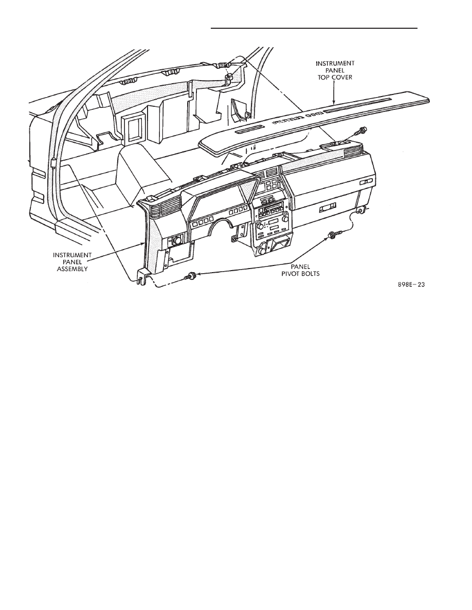
(11) Remove instrument panel top cover (Fig. 28).
(12) Remove lower steering column cover.
(13) Disconnect the steering column wiring at the
25-way connector.
(14) Disconnect park brake, stop lamp and speed
control wiring.
(15) Remove five steering column support nuts and
lower steering column. Then remove two steering col-
umn attaching studs.
(16) Disconnect engine harness wiring at 18-way
and 16-way connectors located on the left side panel
support bracket.
(17) Remove glove box assembly.
(18) Remove the panel top cover assembly.
(19) Loosen the panel roll-down pivot bolts.
(20) Remove the defroster duct adapter from de-
froster duct.
(21) Remove screws which attach instrument panel
to windshield fence line. Roll panel down, attach
heavy wire to hold in position and remove defroster
duct retaining screws.
(22) Disconnect body wiring at the right side
18-way connector and left side 25-way connector.
(23) Disconnect temperature mode cable at in-line
connector. Disconnect resistor block and blower mo-
tor wiring connectors.
Fig. 28 Instrument Panel and Top Cover
8E - 72
INSTRUMENT PANEL AND GAUGES
Ä
(24) Disconnect antenna cable.
(25) Disconnect left and right demister hoses from
demister outlets on the panel.
(26) Remove instrument panel from vehicle.
(27) For installation reverse above procedures.
INTERIOR LAMP REPLACEMENT
The Dome Lamp operates when the doors are open
or headlamp switch is placed in courtesy position.
DOME LAMP
(1) Pry the forward or rearward edge of the dome
lamp to free it from the retaining bracket.
(2) Pry either the forward or rearward edge of the
lens away from the bezel and replace lamp.
(3) For installation, snap lens into bezel and then
bezel into bracket.
TRUNK LAMP
Pry along rearward portion of lens and pivot out of
trunk trim panel. Remove lens and replace lamp.
For installation, snap lens into trunk trim panel.
Ä
INSTRUMENT PANEL AND GAUGES
8E - 73
AUDIO SYSTEM
CONTENTS
page
page
ANTENNAS
. . . . . . . . . . . . . . . . . . . . . . . . . . . . 20
COMPACT DISC PLAYER
. . . . . . . . . . . . . . . . . 30
RADIOS
. . . . . . . . . . . . . . . . . . . . . . . . . . . . . . . . 1
SPEAKERS
. . . . . . . . . . . . . . . . . . . . . . . . . . . . 24
RADIOS
INDEX
page
page
Audio Diagnostic Test Procedures
. . . . . . . . . . . . . 1
Description
. . . . . . . . . . . . . . . . . . . . . . . . . . . . . . 1
Interference Elimination
. . . . . . . . . . . . . . . . . . . . . 1
Radio Removal AP Body Replacement
. . . . . . . . 19
Radio Removal—AA Body
. . . . . . . . . . . . . . . . . . 18
Radio Removal—AC and AY Bodies
. . . . . . . . . . 18
Radio Removal—AG and AJ Bodies
. . . . . . . . . . 18
DESCRIPTION
For operation of the factory installed standard and
optional radios and the optional compact disc player,
refer to the Sound Systems Operating Instructions
Manual supplied with the vehicle.
All vehicles are equipped with an Ignition-Off
Draw Connector which, is used when the vehicles are
originally shipped from the factory. This connector
which, is located near the battery, helps to prevent
battery discharge during storage. For specific connec-
tor type and location, refer to Group 8W, Wiring Di-
agrams.
This connector is included in the radio memory cir-
cuitry and should be checked if the memory of time
or radio station programming is inoperative.
INTERFERENCE ELIMINATION
Some components are used on vehicles equipped
with a radio capacitor, to suppress radio frequency
interference/static.
Capacitors are mounted in various locations, on the
generator either internal or external, internal to the
instrument cluster, and internal to the windshield
wiper motor.
Ground straps are mounted from radio chassis to
instrument panel support structure, engine to cowl,
across engine mount on right hand side. On vehicles
with air conditioning there is a strap from evapora-
tor valve to cowl. These ground straps should be se-
curely tightened to assure good metal to metal
contact. Ground straps conduct very small high fre-
quency electrical signals to ground and require clean
large surface area contact.
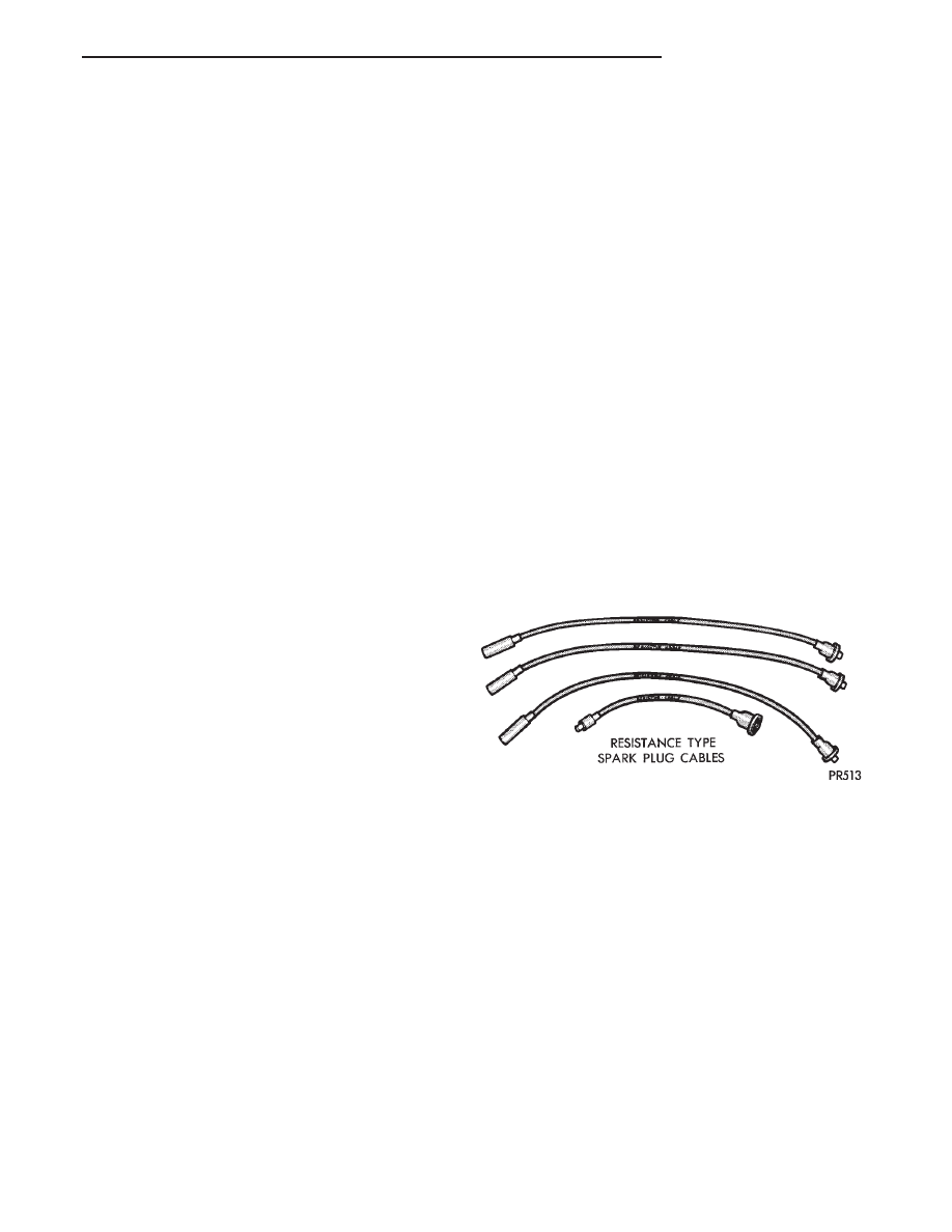
Radio resistance type spark plug cables in the high
tension circuit of the ignition system complete the in-
terference suppression (Fig. 1).
If radio noises are evident, be sure the capacitor
lead wires are making good contact on their respec-
tive terminals and are securely mounted. Faulty or
deteriorated spark plug wires should be replaced.
AUDIO DIAGNOSTIC TEST PROCEDURES
Whenever a audio malfunction occurs, first verify
that the radio wire harness is properly connected to
all connectors before starting normal diagnosis and
repair procedures. Refer to Audio Diagnostic Charts
and/or Radio Connector Circuit Chart (Fig. 2).
Fig. 1 Resistance Type Spark Plug Cables
Ä
AUDIO SYSTEM
8F - 1
Нет комментариевНе стесняйтесь поделиться с нами вашим ценным мнением.
Текст