Chrysler Le Baron, Dodge Dynasty, Plymouth Acclaim. Manual — part 314
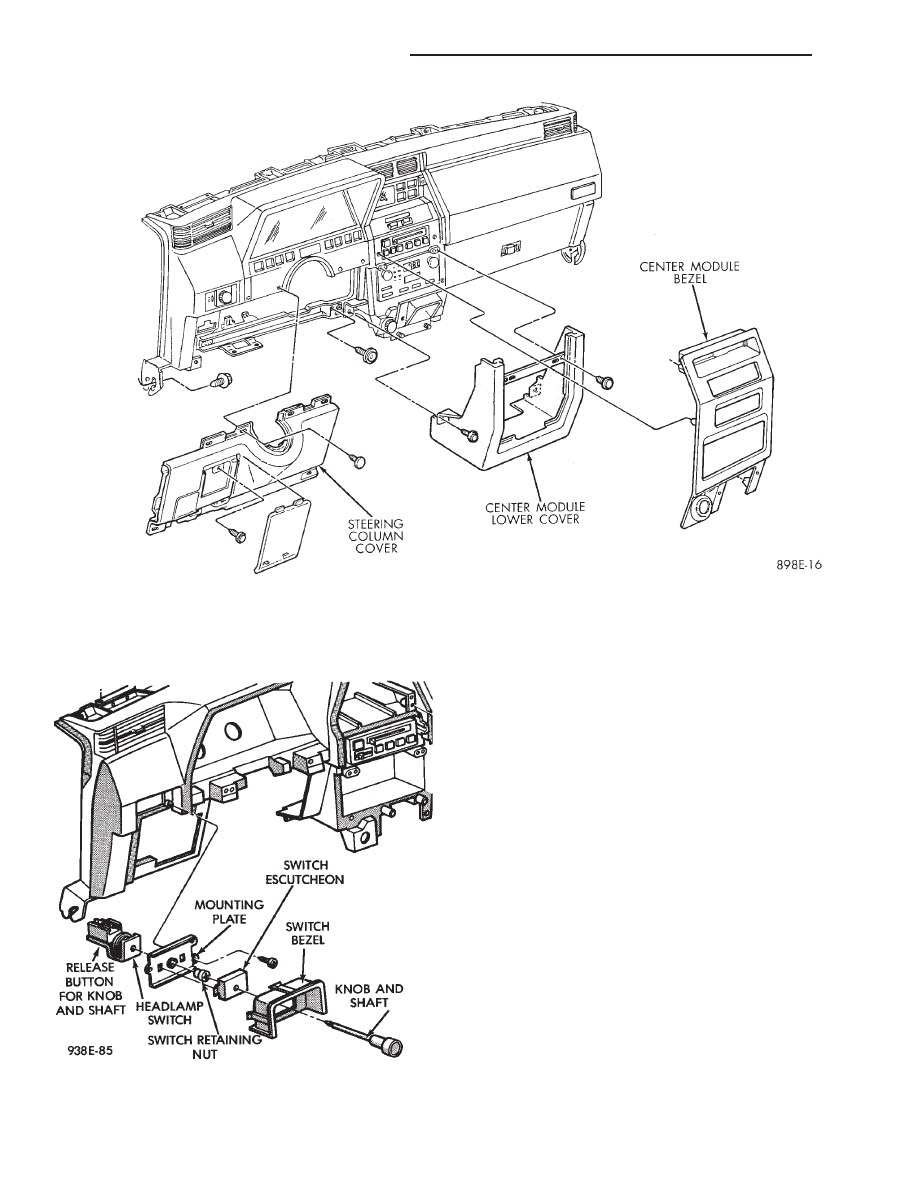
HEADLAMP SWITCH REPLACEMENT
(1) Snap headlamp switch bezel out of instrument
panel pad (Fig. 21).
(2) Remove three screws securing headlamp switch
mounting plate to instrument panel.
(3) Pull headlamp switch and mounting plate rear-
ward from instrument panel opening.
(4) Disconnect wiring connector from switch.
(5) Remove switch knob by depressing release but-
ton on the bottom on the switch and pulling knob out
from switch.
(6) Snap
headlamp
switch
escutcheon
out
of
mounting plate to gain access to mounting plate re-
taining nut.
(7) Remove headlamp switch to mounting plate re-
taining nut and separate switch from mounting
plate.
(8) For installation reverse above procedures.
A/C HEATER CONTROL REPLACEMENT
(1) Remove center bezel assembly.
(2) Remove A/C control to instrument panel retain-
ing screws (Fig. 22).
(3) Pull control rearward and disconnect tempera-
ture control cable and electrical and vacuum connec-
tors.
(4) Remove control from vehicle.
(5) For installation reverse above procedures.
Fig. 20 Lower Instrument Panel
Fig. 21 Headlamp Switch Assembly
8E - 68
INSTRUMENT PANEL AND GAUGES
Ä

HEATER CONTROL LAMP REPLACEMENT
(1) Remove heater control. Refer to A/C Heater
Control for removal.
(2) Pull control far enough to gain access to the
lamp socket.
(3) Replace lamp. To remove lamp rotate socket
counter clockwise. To install rotate clockwise.
(4) For installation reverse above procedures.
A/C CONTROL LAMP REPLACEMENT
(1) Remove heater control. Refer to A/C Heater
Control for removal.
(2) Pry temperature and blower switch knobs off
with flat blade tool. To protect cosmetic face place
cardboard or similar material on the face plate while
prying.
(3) Remove face plate by lifting on the six tabs.
Three on top and three on bottom of the face plate.
(4) Replace lamp.
(5) For installation reverse above procedures.
HEATER CONTROL BLOWER SWITCH
REPLACEMENT
(1) Remove heater control. Refer to A/C Heater
Control for removal.
(2) Pry temperature and blower switch knobs off
with flat blade tool. To protect cosmetic face place
cardboard or similar material on the face plate while
prying.
(3) Remove face plate by lifting on the six tabs.
Three on top and three on bottom of the face plate.
(4) Pry blower switch off with flat blade tool. To
protect cosmetic face, place cardboard or similar ma-
terial on the face plate while prying.
(5) To replace, line up blower switch terminals and
press firmly until the it bottoms out on the housing.
(6) For installation reverse above procedures.
A/C CONTROL BLOWER SWITCH
REPLACEMENT
(1) Remove heater control. Refer to A/C Heater
Control for removal.
(2) Position the temperature knob at the maximum
heat position to gain screw access.
(3) Remove two screws holding the blower switch
located on top of the control.
(4) Pry the blower switch off with a flat blade tool.
(5) To replace, line up blower switch terminals and
press firmly until the it bottoms out on the housing.
(6) For installation reverse above procedures.
GLOVE BOX MODULE REPLACEMENT
(1) Disconnect battery negative cable and isolate
or remove fuse #13 prior to removing switch or wires
may short to ground.
(2) Open glove box door (Fig. 23).
(3) Remove check strap screws to allow full down-
ward movement of the glove box door.
(4) Remove six screws attaching glove box module
to instrument panel.
(5) Pull glove box module rearward and disconnect
wiring from lamp and switch.
(6) Remove glove box from vehicle.
(7) For
installation
reverse
above
procedures.
When installing glove box module, be sure that left
edge of module is pressed against foam bead on trim
pad. This will assure that there will be an adequate
gap between right edge of glove box door and trim
pad.
ASH RECEIVER ASSEMBLY REPLACEMENT
(1) Open ash receiver and remove center module
bezel.
(2) Remove ash receiver bracket to instrument
panel retaining screws (Fig. 23).
(3) Pull assembly rearward off of locating pins and
disconnect wiring for lamp.
(4) Remove ash receiver from vehicle.
(5) For installation reverse above procedures.
Fig. 22 A/C Heater Control
Fig. 23 Glove Box, Ash Receiver and Cigar Lighter
Ä
INSTRUMENT PANEL AND GAUGES
8E - 69
CIGAR LIGHTER REPLACEMENT
(1) Remove center bezel assembly (Fig. 23).
(2) Remove center module lower cover or open for-
ward console lid.
(3) Unscrew lighter receptacle shell from recepta-
cle and remove from base instrument panel.
(4) Disconnect wiring connectors from lighter re-
ceptacle and remove from vehicle.
(5) For installation reverse above procedures.
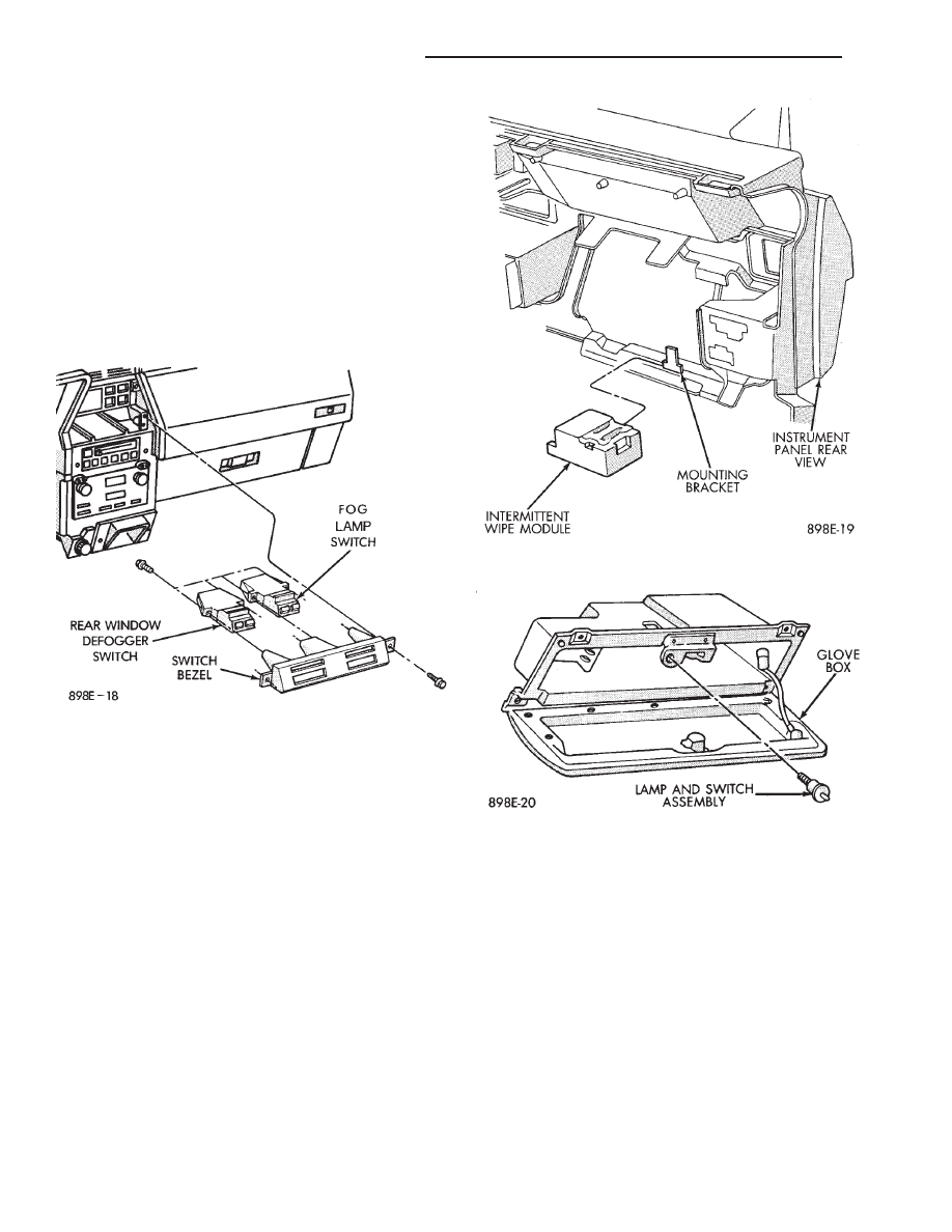
REAR WINDOW DEFOGGER AND/OR FOG
LAMP SWITCH REPLACEMENT
(1) Remove center module bezel assembly (Fig. 20).
(2) Remove two switch bezel screws (Fig. 24).
(3) Pull switches and bezel rearward and discon-
nect wiring connector.
(4) Remove two switch retaining screws.
(5) Remove switch from bezel.
(6) For installation reverse above procedures.
INTERMITTENT WIPE MODULE
REPLACEMENT
(1) Remove lower steering column cover.
(2) Slide intermittent wipe module off of bracket
located on steering column reinforcement (Fig. 25).
(3) Disconnect wiring connector from module and
remove module from vehicle.
(4) For installation reverse above procedures.
GLOVE BOX LAMP AND SWITCH
REPLACEMENT
(1) Disconnect battery and/or pull fuse # 13 before
starting removal procedure.
(2) Open glove box door (Fig. 26).
(3) Carefully pry lamp from its mounting surface
with tip of a small screwdriver.
(4) Pull lamp from box and disconnect electrical
leads.
(5) Remove lamp.
(6) For installation reverse above procedures.
CONSOLETTE ASSEMBLY REPLACEMENT
(1) Remove shifter handle.
(2) Unsnap transmission range indicator bezel or
shift boot bezel from consolette, disconnect wiring
and remove bezel assembly (Fig. 27).
(3) Remove two screws from side of armrest.
(4) Remove
four
caps
which
cover
attaching
screws.
(5) Remove four attaching screws.
(6) Lift consolette up and over shift mechanism to
remove.
(7) For installation reverse above procedures.
Fig. 24 Rear Window Defogger and Fog Lamp
Switch
Fig. 25 Intermittent Wipe Module
Fig. 26 Glove Box Lamp and Switch
8E - 70
INSTRUMENT PANEL AND GAUGES
Ä
CENTER CONSOLE ASSEMBLY
REPLACEMENT
(1) Place transmission in neutral and remove
shifter handle.
(2) Unsnap transmission range indication bezel or
shift boot bezel from console, disconnect wiring and
remove bezel assembly (Fig. 27).
(3) Unsnap power window/mirror switch bezel,
when so equipped and disconnect switch wiring.
(4) Remove two screws from side of armrest.
(5) Remove arm rest and center console section as
a unit by lifting from the front and unsnapping from
front console section.
(6) For installation reverse above procedures. Ad-
just transmission range indicator in the PARK posi-
tion.
CONSOLE GEAR SELECTOR INDICATOR LAMP
REPLACEMENT
(1) Place shifter handle in Neutral position.
(2) Remove handle from shifter.
(3) Unsnap gear selector bezel and pull upward
(Fig. 27).
(4) Remove indicator lamp socket from bezel to re-
place lamp.
(5) For installation reverse above procedures. Ad-
just transmission range indicator in the PARK posi-
tion.
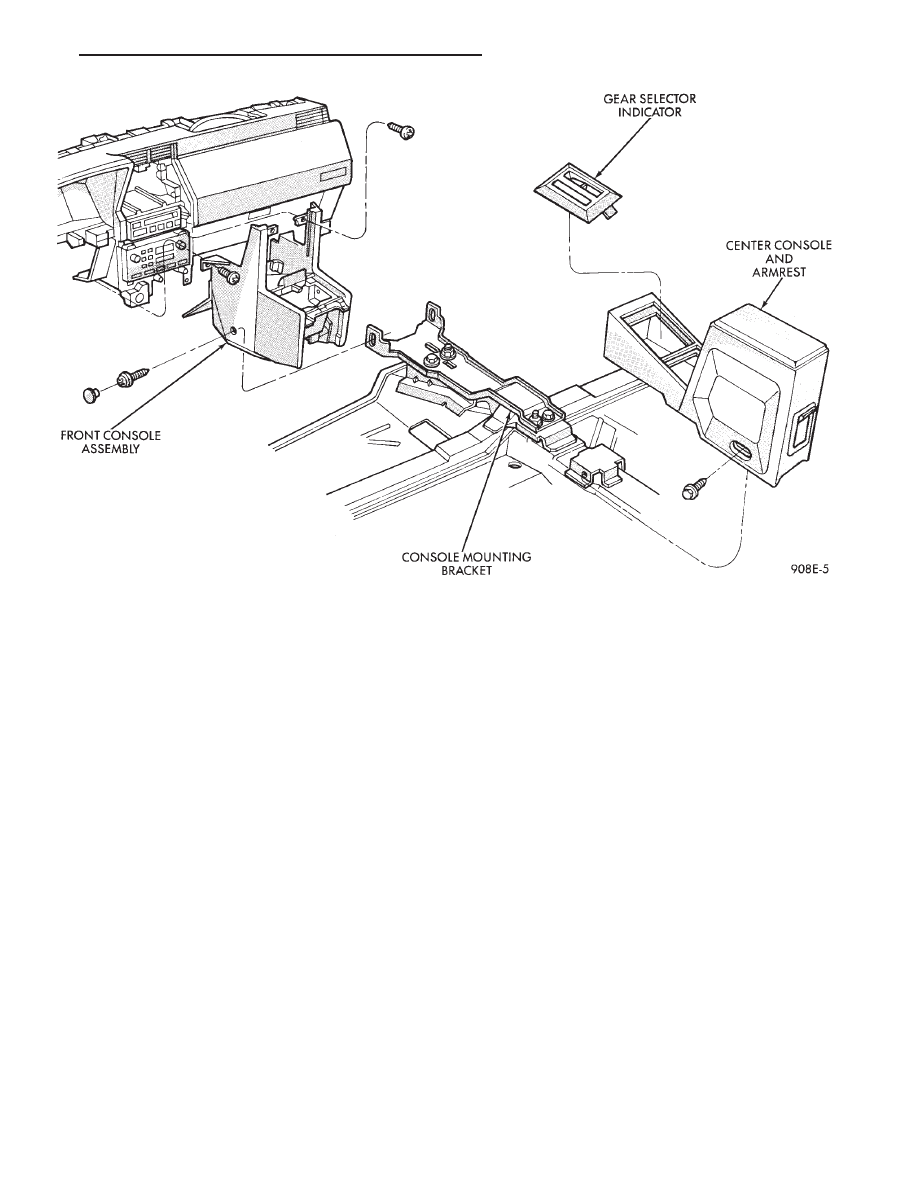
FRONT CONSOLE ASSEMBLY REPLACEMENT
(1) Remove shifter handle.
(2) Unsnap transmission range indicator bezel or
shift boot bezel from console assembly, disconnect
wiring and remove bezel assembly (Fig. 27).
(3) Unsnap power mirror/window switch bezel,
when so equipped and disconnect switch wiring.
(4) Open arm rest and remove three screws hold-
ing arm rest to center console retractor bracket.
(5) Remove armrest and center console section as a
unit by lifting and unsnapping from forward console
section.
(6) Remove center module bezel.
(7) Remove forward console and side walls as com-
plete unit by removing six sidewall attaching screws
to instrument panel and console bracket. Slide unit
rearward and lift to remove.
(8) For installation reverse above procedures.
(a) For adjustment move gearshift lever with
force into park position.
(b) Check gear selector indicator for proper
alignment.
INSTRUMENT PANEL TOP COVER
REPLACEMENT
(1) Place trim-stick tool in groove between the
panel top cover and pad surface (FIG. 28).
Fig. 27 Front and Center Console with Transmission Range Indicator
Ä
INSTRUMENT PANEL AND GAUGES
8E - 71
Нет комментариевНе стесняйтесь поделиться с нами вашим ценным мнением.
Текст