Chrysler Le Baron, Dodge Dynasty, Plymouth Acclaim. Manual — part 326
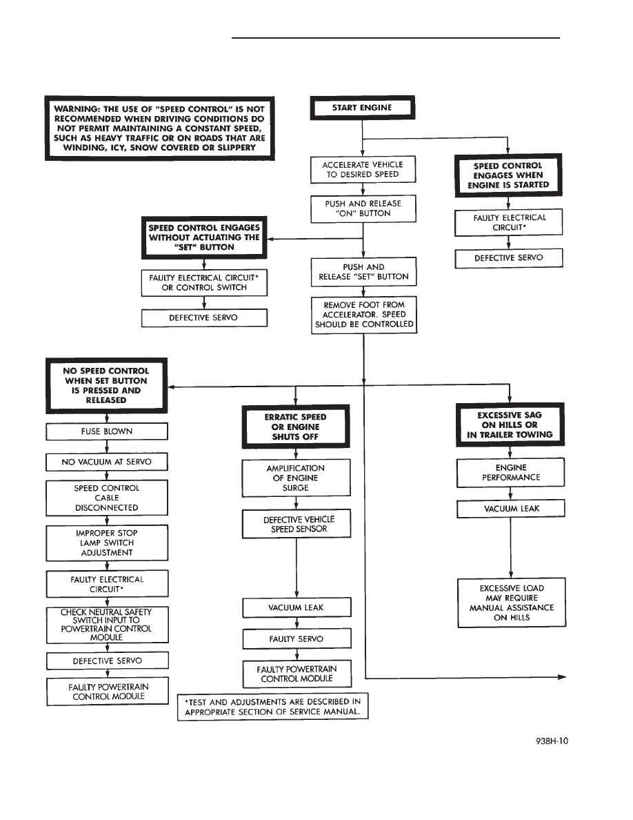
Fig. 9 System Diagnosis
8H - 6
VEHICLE SPEED CONTROL
Ä
(13) Using an ohmmeter, connect one lead to a
good body ground and touch the other lead to pin 29.
When the pedal is depressed, the meter should show
no continuity. With the brake pedal released, the
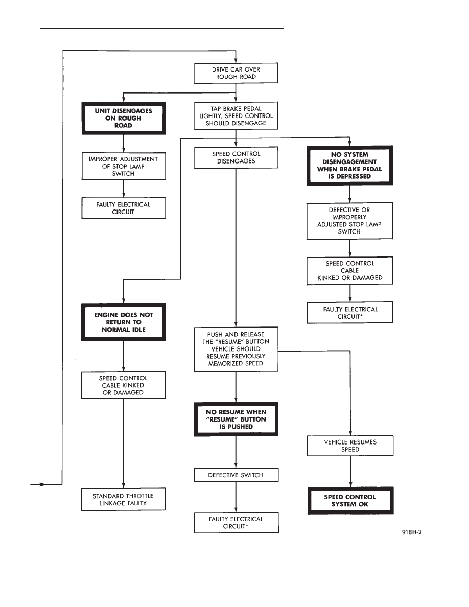
Fig. 10 System Diagnosis—Continued
Ä
VEHICLE SPEED CONTROL
8H - 7
meter should show continuity. If no continuity per-
form the following test. Continuity OK, go to step 12.
(a) Using an ohmmeter test continuity between
pin 29 of powertrain control module and pin 3 of
the stop lamp switch connector.
(b) If no continuity, repair as necessary.
(c) If continuity, refer to Stop Lamp Switch Test.
(d) If stop lamp switch test OK, Test continuity
between pin 6 of stop lamp switch and ground.
(14) Using an ohmmeter, touch one lead to a good
body ground and touch the other lead to pin 30. The
meter should show no continuity when transmission
is in DRIVE and continuity when in PARK or NEU-
TRAL. If not test Neutral Start and Back-Up switch
using DRB II.
VEHICLE SPEED CONTROL SWITCH TEST
WARNING: IF REMOVAL OF AIR BAG MODULE IS
NECESSARY, REFER TO GROUP 8M, RESTRAINT
SYSTEMS.
(1) Remove the switch and disconnect 4-way con-
nector.
(2) Using an ohmmeter, test continuity at the four
pins of the vehicle speed control switch. Refer to Ve-
hicle Speed Control Switch Continuity (Fig. 15).
(3) If there is no continuity or incorrect continuity
at any one of the switch positions, replace the switch.
STOP LAMP VEHICLE SPEED CONTROL SWITCH
TEST
(1) Disconnect the six way connector at the stop
lamp switch (Fig.16). Using an ohmmeter, continuity
may be checked at the switch side of the connector as
follows:
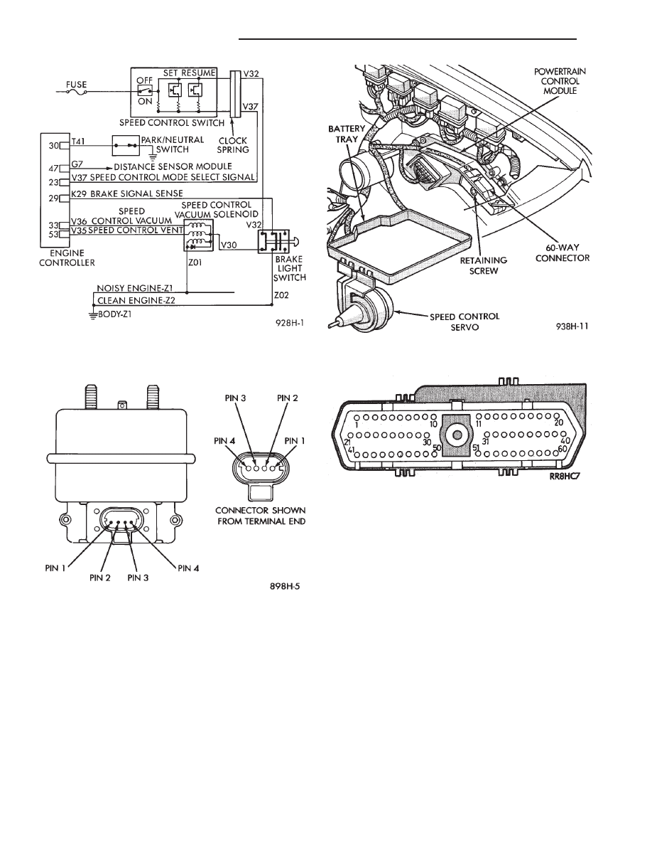
Fig. 11 Vehicle Speed Control Circuit
Fig. 12 Servo Harness Connector
Fig. 13 Powertrain Control Module and Connector
Location
Fig. 14 Powertrain Control Module 60-Way
Connector Shown from Terminal End
8H - 8
VEHICLE SPEED CONTROL
Ä
(a) With brake pedal released, there should be
continuity:
• Between pin 1 and pin 4
• Between pin 3 and pin 6
• No continuity between pin 2 and pin 5
(b) With brake pedal depressed, there should be
no continuity:
• Between pin 1 and pin 4
• Between pin 3 and pin 6
• Continuity between pin 2 and pin 5
(2) If the above results are not obtained, the stop
lamp switch is defective or out of adjustment.
(3) Stop lamp switch adjustment is detailed in
Group 5, Brakes.
VACUUM SUPPLY TEST
(1) Disconnect vacuum hose at the servo and in-
stall a vacuum gauge in the hose (Fig. 17).
(2) Start engine and observe gauge at idle. Vac-
uum gauge should read at least ten inches of mer-
cury. Shut off engine, the vacuum should continue to
hold 10 inches of mercury.
(3) If vacuum does not meet this requirement,
check and correct the following vacuum leaks:
• Vacuum lines
• Check valve
• Vacuum reservoir
• Servo, refer to Servo Vacuum Test
• Poor engine performance
SERVO VACUUM TEST
(1) Remove the vehicle speed control cable at the
throttle body end.
(2) Disconnect the 4-way electrical connector and
the vacuum harness at the servo (Refer to Fig. 12).
(3) Connect battery voltage to pin 2 of the servo.
(4) Ground the remaining three servo pins 1, 3 and
4.
(5) Connect a hand held vacuum pump to the servo
vacuum nipple and apply 10 to 15 inches of vacuum.
(6) The cable should pull in and hold for as long as
vacuum is applied.
SERVO UNIT
REMOVAL
(1) Remove two nuts attaching vehicle speed con-
trol cable and mounting bracket to servo.
(2) Remove
screws
attaching
servo
mounting
bracket.
(3) Remove servo mounting bracket.
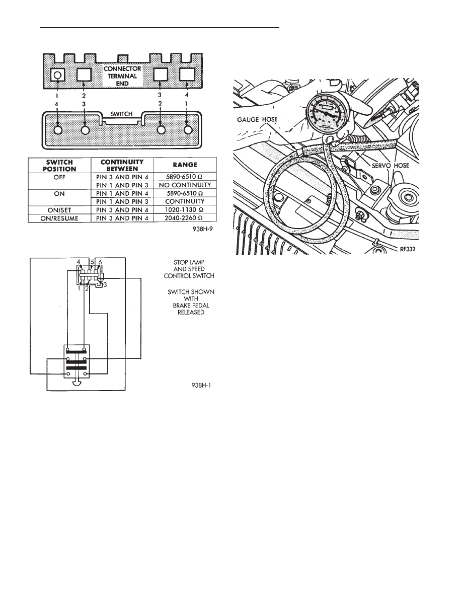
Fig. 15 Vehicle Speed Control Switch Continuity
Fig. 16 Stop Lamp and Vehicle Speed Control
Switch Wiring
Fig. 17 Vacuum Gauge Test
Ä
VEHICLE SPEED CONTROL
8H - 9
Нет комментариевНе стесняйтесь поделиться с нами вашим ценным мнением.
Текст