Chrysler Le Baron, Dodge Dynasty, Plymouth Acclaim. Manual — part 325
TO RESUME: After disengaging the vehicle speed
control by tapping the brake pedal or clutch pedal,
push the RESUME/ACCEL button to return vehicle
to the previously set speed.
TO ACCELERATE: While vehicle speed control is
engaged, hold the RESUME/ACCEL button de-
pressed and release at a new desired speed. This will
allow the vehicle to continuously accelerate and set
at a higher speed setting.
TAP-UP: When the vehicle speed control is en-
gaged, tapping the RESUME/ACCEL button will in-
crease the speed setting by 2 mph (3 km/h). The
system will respond to multiple tap-ups.
TO ACCELERATE for PASSING: Depress the
accelerator as you would normally. When the pedal
is released the vehicle will return to the speed set-
ting in memory.
DIAGNOSIS PROCEDURES
Whenever a vehicle speed control malfunction oc-
curs, first verify that the vehicle speed control wire
harness is properly connected to all connectors before
starting normal diagnosis and repair procedures. Re-
fer to Electronic Vehicle Speed Control Diagnosis
Chart or Vehicle Speed Control Circuit (Fig. 9, 10
and 11).
A poor connection can cause a complete or inter-
mittent malfunction and is also the only connection
in the circuit, that can not be tested. For this reason,
a loose connection may be misdiagnosed as a compo-
nent malfunction.
Also, check all vacuum connections for tightness
and cracked hoses.
ROAD TEST
Road test vehicle to verify reports of vehicle speed
control malfunction. The road test should include at-
tention to the speedometer. Speedometer operation
should be smooth and without flutter at all speeds.
Flutter in the speedometer indicates a problem
which might cause surging in the vehicle speed con-
trol. The cause of any speedometer deficiencies
should be corrected before proceeding.
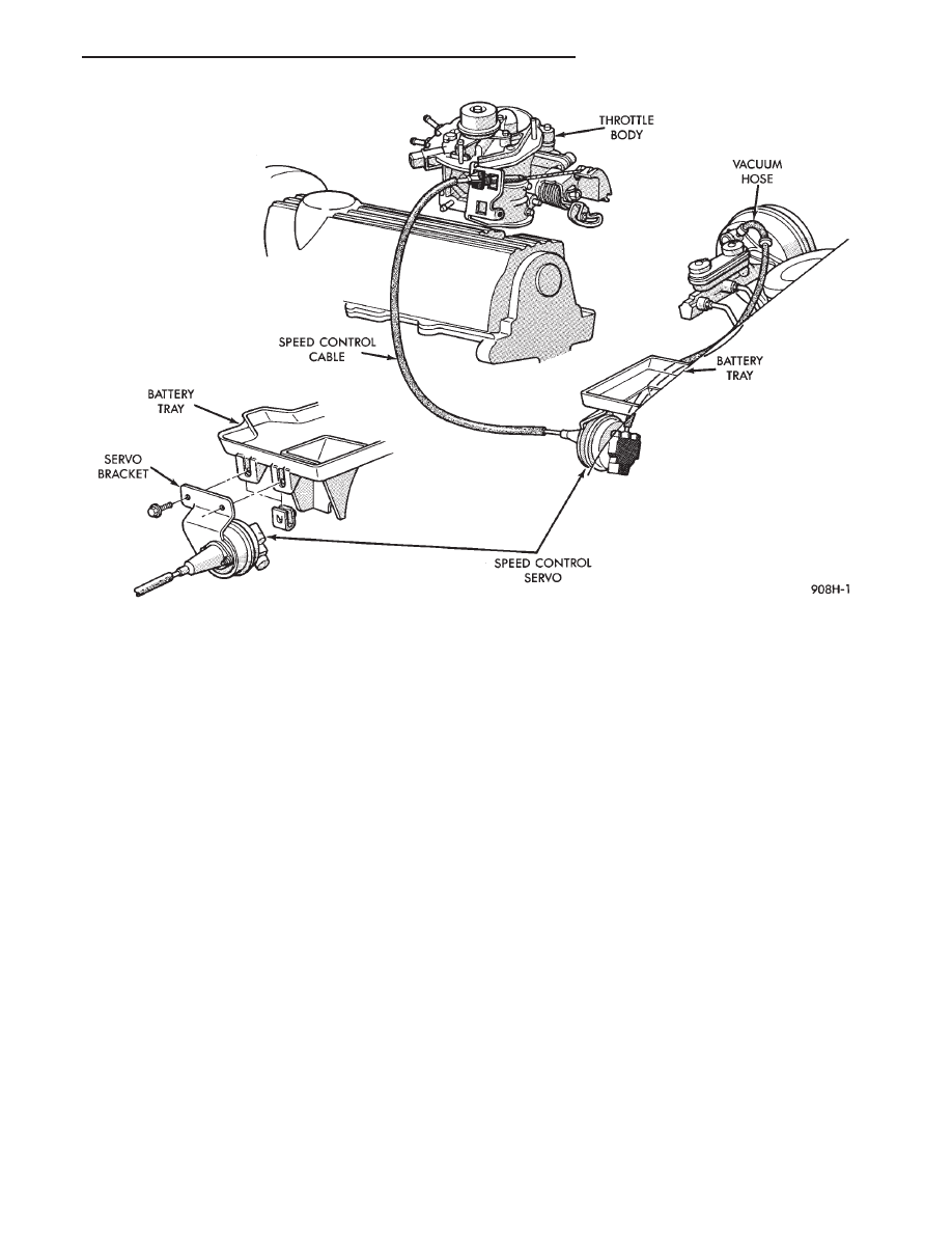
Fig. 3 Vehicle Speed Control—Turbo
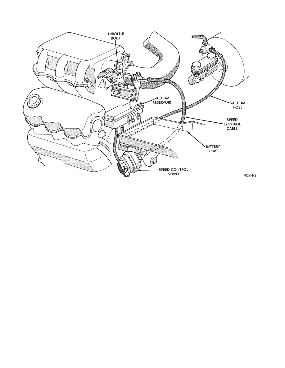
Fig. 4 Vehicle Speed Control—3.0L
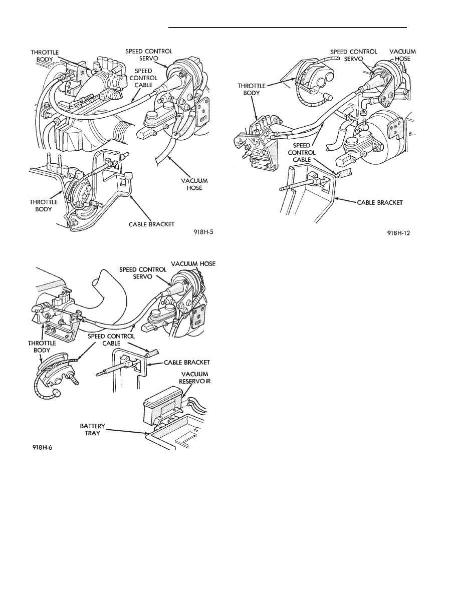
Fig. 5 Vehicle Speed Control—2.2L Turbo III
8H - 2
VEHICLE SPEED CONTROL
Ä
INOPERATIVE SYSTEM
If road test verifies an inoperative system with a
correct speedometer operation:
• Inspect fuse
• Check for loose electrical and vacuum connections
at the servo
• Check for correct position of the vacuum check
valve in the hose from servo to vacuum source. The
word VAC on the valve must point toward the vac-
uum source.
• Inspection should also be made to verify that both
ends of the vehicle speed control cable are securely
attached. If either end is loose, the vehicle speed con-
trol will be inoperative.
CHECKING FOR FAULT CODE
(1) When trying to verify a vehicle speed control
electronic malfunction:
(a) Connect a DRB II if available.
(b) Plug DRB II into the diagnostic connector in
the engine compartment.
(c) Check that either a Fault Code 34 or Fault
Code 15 is indicated.
(d) An inoperative vehicle speed control may still
occur without either fault code being indicated.
(e) With key inserted in ignition switch, cycle
switch to ON position three times. On third cycle,
leave switch in ON position.
(f) After switch has been cycled three times, ob-
serve CHECK ENGINE indicator on instrument
cluster. If a Fault Code is present, indicator will
flash (blink) in a series which will show which
Fault Code is the problem. EXAMPLE: A series of
three flashes in rapid succession, a slight pause,
then four flashes in rapid succession would indicate
Fault Code 34.
(2) If no Fault Code appears, or Fault Code 34 is
observed, refer to:
• The Servo Electrical Test.
• The Powertrain Control Module Electrical Test.
(3) If a fault code 15 is observed, test vehicle speed
sensor.
For testing vehicle speed sensor and related compo-
nents refer to the Powertrain Diagnostics Test Proce-
dure Manual.
(4) Correct any problems found when performing
these tests and recheck for Fault Code if changes
were made.
(5) If no problems were found above, replace pow-
ertrain control module.
VEHICLE SPEED CONTROL ELECTRICAL TESTS
WARNING: IF REMOVAL OF AIR BAG MODULE IS
NECESSARY, REFER TO GROUP 8M, RESTRAINT
SYSTEMS.
Fig. 6 Vehicle Speed Control—AC & AY Bodies with 2.5L
Ä
VEHICLE SPEED CONTROL
8H - 3
Electronic vehicle speed control may be tested us-
ing two different methods. One involves use of a
DRB II. If this test method is desired, refer to the
Powertrain Diagnostic Test Procedures for charging
and vehicle speed control manual.
The other test method uses a volt/ohm meter and is
described in the following tests.
If any information is needed concerning wiring, re-
fer to Group 8W, Wiring Diagrams.
CAUTION: When test probing for voltage or conti-
nuity at electrical connectors, care must be taken
not to damage connector, terminals, or seals. If
these components are damaged, intermittent or
complete system failure may occur.
SERVO ELECTRICAL TESTS
WARNING: ON VEHICLES EQUIPPED WITH AIR-
BAG, SEE GROUP 8M, RESTRAINT SYSTEMS FOR
AIRBAG,
STEERING
WHEEL
OR
COLUMN
RE-
MOVAL PROCEDURES.
(1) Turn ignition switch to the ON position. With
the vehicle speed control switch in the ON position,
set up a voltmeter to read battery voltage and con-
nect the negative lead to a good chassis ground.
(2) Disconnect the four-way connector going to the
servo (Fig. 12). Test pin 2 of the main harness four-
way connector for battery voltage. If not OK go to
step 3. If voltage is OK go to step 4.
(3) Perform the following tests.
(a) Disconnect the six-way connector at the stop
lamp switch and test pin 1 of the main harness for
battery voltage. If voltage is OK perform the stop
lamp switch test.
(b) If the stop lamp switch tests OK; repair wire
between the servo and the stop lamp switch.
(c) If no voltage at pin 1 at the 6-way stop lamp
connector, remove the vehicle speed control switch
and disconnect the four-way connector. Test pin 1
of main harness for battery voltage.
(d) If voltage is OK perform the vehicle speed
control switch test.
(e) If vehicle speed control switch is OK, test
continuity across the clockspring.
(f) If clockspring OK, repair as required, wire be-
tween stop lamp switch and clockspring.
(g) If no voltage at pin 1 of the 4-way vehicle
speed control switch connector.
• Test for battery voltage between the ignition and
the fuse
• If voltage OK, check fuse
• If fuse OK, repair wire between fuse and clock-
spring
Fig. 7 Vehicle Speed Control—AC & AY Bodies with 3.0L
8H - 4
VEHICLE SPEED CONTROL
Ä

(4) Connect a jumper wire between pin 2 of the
four-way servo connector of the main harness and
pin 2 of the vehicle speed control servo (Fig. 12). The
other three pins from the servo should show battery
voltage. If not, replace the servo.
(5) Using an ohmmeter, connect one lead to a good
body ground and the other lead touch pin 1 in the
four-way servo connector of the main harness. The
meter should show continuity. If not, repair the
ground circuit as necessary.
POWERTRAIN CONTROL MODULE ELECTRICAL
TEST
WARNING: ON VEHICLES EQUIPPED WITH AIR-
BAG, SEE GROUP 8M, RESTRAINT SYSTEMS FOR
AIRBAG,
STEERING
WHEEL
OR
COLUMN
RE-
MOVAL PROCEDURES.
(1) Unplug 60-way connector from the powertrain
control module, located next to the battery (Fig. 13).
(2) Remove vehicle speed control switch. Refer to
Vehicle Speed Control Switch Removal. Disconnect
the 4-way connector.
(3) Using an ohmmeter test continuity between pin
23 of powertrain control module and pin 4 of the ve-
hicle speed control switch harness. Refer to Fig. 14
for controller terminal locations.
(a) If no continuity, repair wire circuit as neces-
sary.
(b) Continuity OK, refer to Vehicle Speed Con-
trol Switch Test.
(4) Connect the 4-way connector to vehicle speed
control switch.
(5) Connect negative lead of voltmeter to a good
body ground near the powertrain control module.
(6) Turn ignition switch ON.
(7) Place vehicle speed control switch in the OFF
position. Touch the positive lead of the voltmeter to
pin 53, the voltmeter should read 0 volts.
(8) Place vehicle speed control switch in the ON
position. Touch the positive lead of the voltmeter to
pin 53, the voltmeter should read battery voltage.
(9) If no voltage, repair the wire between pin 53
and pin 3 of the vehicle speed control servo (Fig. 6).
If voltage is OK go to step 8.
(10) Place vehicle speed control switch in the OFF
position. Touch the positive lead of the voltmeter to
pin 33, voltmeter should read 0 volts.
(11) Place vehicle speed control switch in the ON
position. Touch the positive lead of the voltmeter to
pin 33, the voltmeter should read battery voltage.
(12) If no voltage, repair the wire between pin 33
and pin 4 of the vehicle speed control servo (Fig. 6).
If voltage is OK go to step 11.
Fig. 8 Vehicle Speed Control—AC & AY Bodies with 3.3/3.8L
Ä
VEHICLE SPEED CONTROL
8H - 5
Нет комментариевНе стесняйтесь поделиться с нами вашим ценным мнением.
Текст