Chrysler Le Baron, Dodge Dynasty, Plymouth Acclaim. Manual — part 64

WARNING: PLACE A SHOP TOWEL UNDER FUEL
PRESSURE REGULATOR TO ABSORB ANY FUEL
SPILLAGE.
(5) Remove fuel pressure regulator and O-rings
(Fig. 16).
INSTALLATION
(1) Ensure fuel pressure regulator has two plastic
spacers (Fig. 16). Place O-rings in the fuel pressure
regulator cavity (Fig. 17). Do not install O-rings on
the fuel pressure regulator.
(2) Insert fuel pressure regulator into the fuel rail.
(3) Install fuel pressure regulator retainer (Fig.
15).
(4) Install retainer screw. Tighten to 7 N
Im (60 in.
lbs.) torque.
(5) Connect vacuum line to the fuel pressure regu-
lator.
CAUTION: When using the ASD Fuel System Test,
the Auto Shutdown (ASD) Relay remains energized
for either 7 minutes, until the test is stopped, or un-
til the ignition switch is turned to the Off position.
(6) With the ignition key in ON position, access
the DRBII scan tool ASD Fuel System Test to pres-
surize the fuel system. Check for leaks.
FUEL INJECTOR
The fuel rail must be removed first. Refer to Fuel
Injector Rail Assembly Removal in this section.
REMOVAL
(1) Disconnect injector wiring connector from injec-
tor.
(2) Position fuel rail assembly so that the fuel in-
jectors are easily accessible (Fig. 18).
Fig. 15 Fuel Pressure Regulator
Fig. 16 Fuel Pressure Regulator
Removal/Installation
Fig. 17 Fuel Pressure Regulator O-Rings
Fig. 18 Fuel Injector and Rail—Typical
14 - 174
FUEL SYSTEMS
Ä
(3) Rotate injector and pull injector out of fuel rail.
The clip will stay on the injector.
(4) Check injector O-ring for damage. If O-ring is
damaged, it must be replaced. If injector is reused, a
protective cap must be installed on the injector tip to
prevent damage. Replace the injector clip if it is
damaged.
(5) Repeat for remaining injectors.
INSTALLATION
(1) Before installing an injector the rubber O-ring
must be lubricated with a drop of clean engine oil to
aid in installation.
(2) Install injector clip by sliding open end into top
slot of the injector. The edge of the receiver cup will
slide into the side slots of clip (Fig. 19).
(3) Install injector top end into fuel rail receiver
cap. Be careful not to damage O-ring during instal-
lation (Fig. 19).
(4) Repeat steps for remaining injectors.
(5) Connect fuel injector wiring.
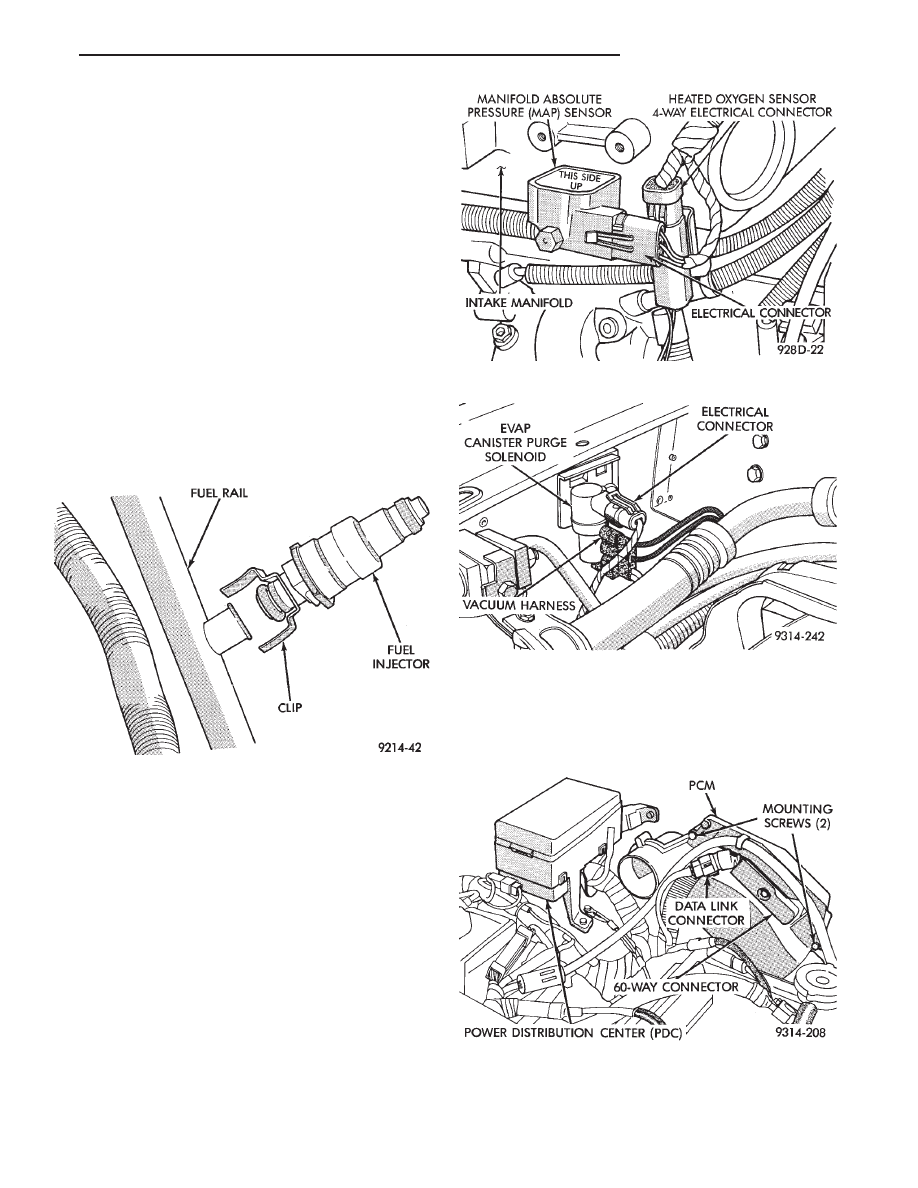
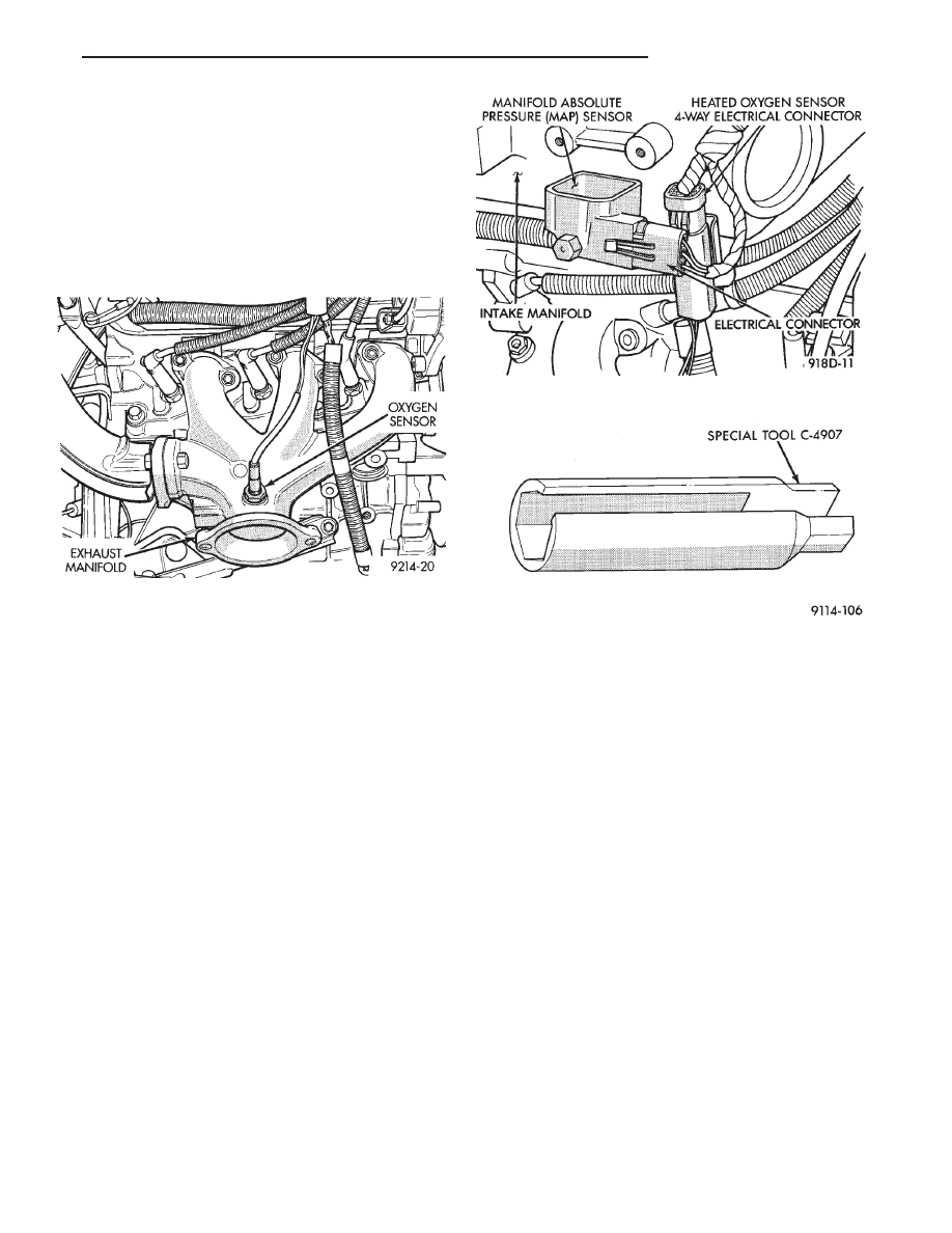
MANIFOLD ABSOLUTE PRESSURE (MAP) SENSOR
The alignment of the MAP sensor is critical to the
sensors performance. The top of the sensor is marked
This Side Up (Fig. 20).
(1) Disconnect electrical connector from MAP sen-
sor.
(2) Remove sensor by unscrewing from the intake
manifold (Fig. 20).
(3) Reverse the above procedure for installation.
EVAP CANISTER PURGE SOLENOID SERVICE
(1) Remove vacuum hose and electrical connector
from solenoid (Fig. 21).
(2) Depress tab on top of solenoid and slide the so-
lenoid downward out of mounting bracket.
(3) Reverse above procedure for installation.
PCM SERVICE
(1) Remove air cleaner duct from PCM.
(2) Remove battery.
(3) Remove PCM mounting screws (Fig. 22).
(4) Remove 60-way electrical connector from PCM.
Fig. 19 Servicing Fuel Injector—Typical
Fig. 20 Manifold Absolute Pressure Sensor
Fig. 21 Canister Purge Solenoid
Fig. 22 PCM Removal
Ä
FUEL SYSTEMS
14 - 175
(5) Reverse the above procedure for installation.
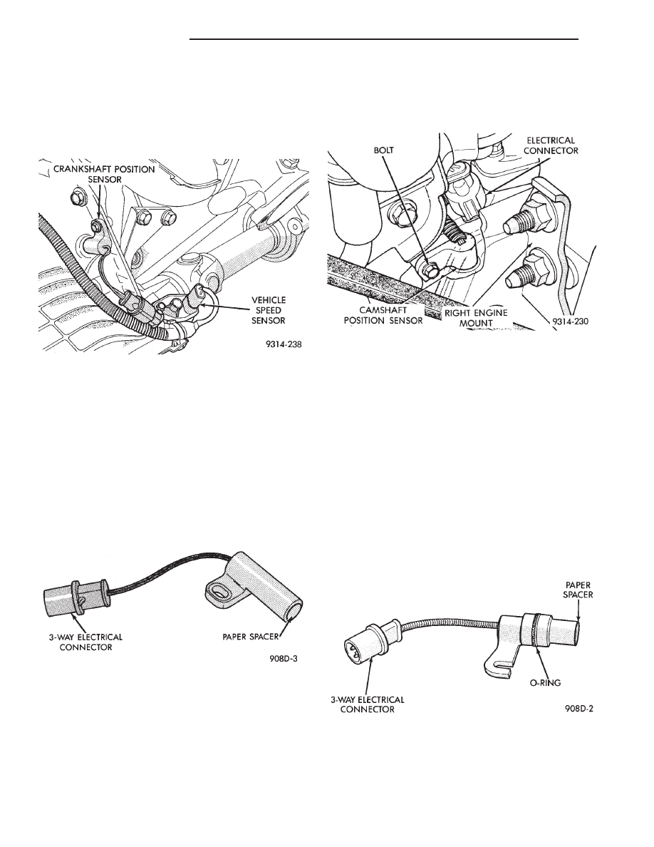
CRANKSHAFT POSITION SENSOR
REMOVAL
(1) Disconnect crankshaft position sensor electrical
connector from the wiring harness connector (Fig. 23).
(2) Remove crankshaft position sensor retaining
bolt.
(3) Pull sensor straight up out of the transaxle
housing.
INSTALLATION
If installing the original sensor, clean off the
old spacer on the sensor face. A NEW SPACER
must be attached to the sensor face before instal-
lation. If the sensor is being replaced, confirm
that the paper spacer is attached to the face of
the new sensor (Fig. 24).
(1) Install sensor in transaxle and push sensor down
until contact is made with the drive plate. While
holding the sensor in this position, and install and
tighten the retaining bolt to 12 N
Im (105 in. lbs.)
torque.
(2) Connect crankshaft position sensor electrical
connector to the wiring harness connector.
CAMSHAFT POSITION SENSOR SERVICE
REMOVAL
(1) Disconnect camshaft position sensor electrical
connector from the wiring harness connector (Fig. 25).
(2) Loosen camshaft position sensor retaining bolt
enough to allow slot in sensor to slide past the bolt.
(3) Pull sensor up out of the chain case cover. Do not
pull on the sensor lead. There is an O-ring on the
sensor case. The O-ring may make removal difficult. A
light tap to top of sensor prior to removal may reduce
force needed for removal.
INSTALLATION
If installing the original sensor, clean off the
old spacer on the sensor face. A NEW SPACER
must be attached to the face before installation.
Inspect O-ring for damage, replace if necessary.
If the sensor is being replaced, confirm that the
paper spacer is attached to the face and O-ring is
positioned in groove of the new sensor (Fig. 26).
(1) Apply a couple drops of clean engine oil to the
O-ring prior to installation. Install sensor in the chain
case cover and push sensor down until contact
Fig. 23 Crankshaft Position Sensor
Fig. 24 Crankshaft Position Sensor and Spacer
Fig. 25 Camshaft Position Sensor
Fig. 26 Camshaft Position Sensor
14 - 176
FUEL SYSTEMS
Ä
is made with the camshaft gear. While holding the
sensor in this position, install and tighten the retain-
ing bolt 12 N
Im (105 in. lbs.) torque.
(2) Connect camshaft position sensor electrical con-
nector to harness connector. Position connector away
from the accessory belt.
HEATED OXYGEN SENSOR (O
2
SENSOR) SERVICE
The oxygen sensor is installed in the exhaust mani-
fold (Fig. 27).
CAUTION: Do not pull on the oxygen sensor wire
when disconnecting the electrical connector.
WARNING: THE EXHAUST MANIFOLD MAY BE EX-
TREMELY HOT. USE CARE WHEN SERVICING THE
OXYGEN SENSOR.
(1) Disconnect oxygen sensor electrical connector
(Fig. 28).
(2) Remove sensor using Tool C-4907 (Fig. 29).
Slightly tightening the sensor can ease removal.
When the sensor is removed, the exhaust manifold
threads must be cleaned with an 18 mm X 1.5 + 6E tap.
If using original sensor, coat the threads with Loctite
771-64 anti-seize compound or equivalent. New sen-
sors are packaged with compound on the threads and
do not require additional compound. The sensor must
be tightened to 27 N
Im (20 ft. lbs.) torque.
Fig. 27 Oxygen Sensor—3.3L Engine
Fig. 28 Oxygen Sensor Connector
Fig. 29 Oxygen Sensor Socket
Ä
FUEL SYSTEMS
14 - 177
Нет комментариевНе стесняйтесь поделиться с нами вашим ценным мнением.
Текст