Chrysler Le Baron, Dodge Dynasty, Plymouth Acclaim. Manual — part 299
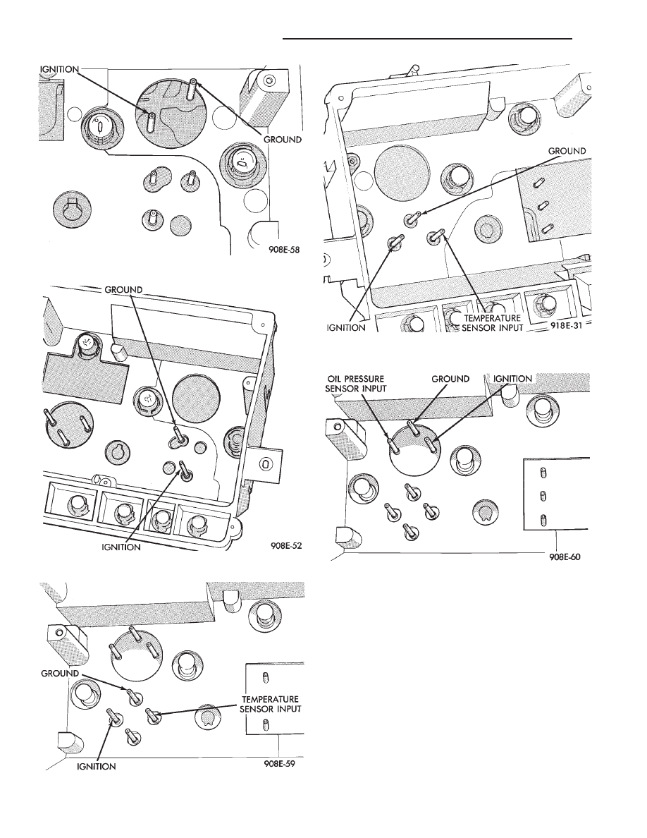
(2) With the ignition key ON, check for ignition
voltage at ignition pin of gauge. Check for ground at
ground pin of gauge. Refer to the individual gauge
circuit test for proper pin.
(a) If voltage at pin, replace gauge.
(b) If no voltage or ground at gauge pins, check
for ignition voltage and ground at cluster harness
connectors.
(c) If no voltage or ground, repair as necessary.
Refer to 8W, Wiring Diagrams.
(d) If there is voltage or ground, check cluster for
distorted terminals. If terminals are OK, replace
printed circuit board.
Fig. 19 Voltmeter Pins—With Tachometer
Fig. 20 Voltmeter Pins—Without Tachometer
Fig. 21 Temperature Gauge Pins—With Tachometer
Fig. 22 Temperature Gauge Pins—Without
Tachometer
Fig. 23 Oil Pressure Gauge Pins—With Tachometer
8E - 8
INSTRUMENT PANEL AND GAUGES
Ä
(3) When testing temperature, allow the engine to
run until the vehicle reaches a normal operating
temperature. Turn ignition OFF, and remove gauge
from cluster.
(a) Testing oil pressure gauge, engine needs to
be running.
(b) Measure and record the resistance between
sending unit pin and ground pin of the gauge in
question. Refer to Gauge Calibration.
(c) It is important to have the same engine tem-
perature and engine speed when checking temper-
ature and oil pressure gauges position. The time
between gauge position reading and sending unit
measuring should be kept to a minimum.
(d) If resistance and gauge position are not sim-
ilar, replace gauge.
(e) If OK, test resistance from the sending unit
to the cluster connector.
(f) If
resistance
reading
is
different,
check
printed circuit board for contact to cluster connec-
tor.
(g) If OK and contacts are not distorted, replace
printed circuit board.
(h) If everything checks out OK, refer to sending
unit test.
(4) If fuel gauge does not meet specifications, refer
to Group 14, Fuel for the test procedure.
GAUGE CALIBRATION
(1) Remove the gauge.
(2) Check for ignition voltage and ground to the
gauge.
(3) With the ignition key in the OFF position, re-
place gauge. Turn the ignition key to the ON posi-
tion. To test oil pressure gauge engine must be
running. When testing oil or temperature gauge the
engine should be at normal operating temperature.
Record the gauge position.
(4) Remove gauge and record the resistance be-
tween the sending unit pin and the gauge ground
pin. When checking gauges, it is important to have
the same engine temperature and speed when noting
gauge position. The time between gauge reading and
measuring should be kept to a minimum.
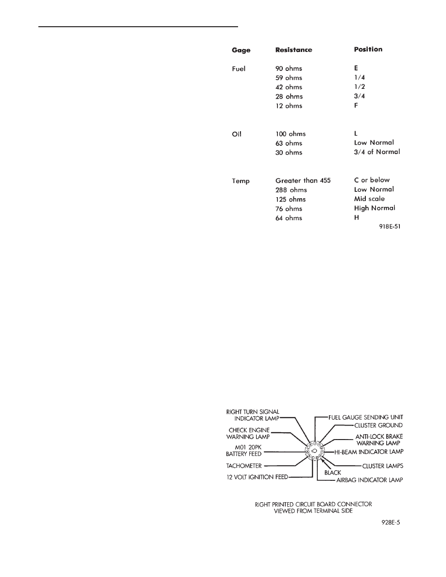
(5) The Gauge Resistance Chart (Fig. 24), is gen-
eral guidelines for checking the gauge position
against the sending unit resistance.
Because of only a few specific points of gauge posi-
tion versus sending unit resistance, a good estimate
is need when the resistance falls between gradua-
tions. Even when the resistance corresponds to grad-
uations, the gauge has a tolerance of
6 4 ohms.
Volt gauge: The calibration dot on the volt gauge
corresponds to 13 volts between the gauge ignition
and ground pins. If voltage varies from this, estimate
proper gauge position with input voltage.
TACHOMETER REPLACEMENT
(1) Remove cluster, radio and rear window defog-
ger bezels and mask/lens assembly.
(2) Remove screws attaching tachometer to cluster
housing.
(3) Pull tachometer rearward to remove.
(4) For installation reverse above procedures.
TACHOMETER CIRCUIT TESTING
(1) Remove cluster, radio and rear window defog-
ger bezels and mask/lens assembly.
(2) Check for battery voltage at cavity A of the in-
strument cluster black connector.
(3) With the ignition in the ON position, check for
battery voltage at cavity C of the black connector
(Fig. 25).
Fig. 24 Gauge Resistance
Fig. 25 Printed Circuit Board 11-Way Connector
Ä
INSTRUMENT PANEL AND GAUGES
8E - 9
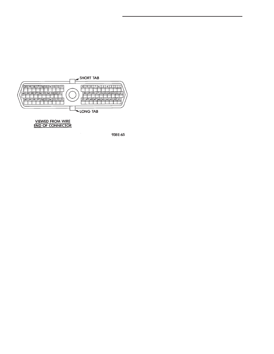
(4) Check cavity H of the black connector for con-
tinuity to ground.
(5) Check for tachometer signal from the power-
train control module by connecting an AC DIGITAL
VOLTMETER to cavity B of the instrument cluster
black connector and ground. A reading of at least 1.0
volt should be present with the engine running (Fig.
26).
(a) If voltage is within specification, go to step 7.
(b) If voltage is NOT within specification, per-
form steps 6.
(6) If there is less than 1.0 volt at cavity B, check
for continuity between cavity B and pin 43 of the
powertrain control module connector.
(a) If continuity is OK, between cavity B and pin
43 of the powertrain control module connector, re-
place the powertrain control module.
(b) No continuity, check the connectors for dam-
aged pins or terminal push outs or defective wire.
(7) If all tests performed test good replace the ta-
chometer drive module.
(8) If the tachometer continues to be inoperative,
replace the tachometer assembly.
VOLTMETER AND FUEL GAUGE ASSEMBLY
REPLACEMENT
(1) Remove cluster, radio and rear window defog-
ger bezels and mask/lens assembly.
(2) Remove tachometer.
(3) Remove screw attaching gauge assembly to
cluster.
(4) Pull rearward to remove gauge assembly.
(5) For installation reverse above procedures.
OIL PRESSURE AND TEMPERATURE GAUGE
ASSEMBLY REPLACEMENT
(1) Remove cluster, radio and rear window defog-
ger bezels and mask/lens.
(2) Remove speedometer.
(3) Remove screw attaching gauge assembly to
cluster.
(4) Pull rearward to remove gauge assembly.
(5) For installation reverse above procedures.
FUEL GAUGE REPLACEMENT
(1) Remove cluster, radio and rear window defog-
ger bezels and mask/lens.
(2) Remove screws attaching fuel gauge to cluster
housing.
(3) Pull fuel gauge rearward to remove.
(4) For installation reverse above procedures.
VOLTMETER GAUGE REPLACEMENT
(1) Remove cluster bezel and mask.
(2) Remove fuel gauge.
(3) Remove screws attaching voltmeter assembly to
cluster.
(4) Pull rearward to remove gauge assembly.
(5) For installation reverse above procedures.
TEMPERATURE GAUGE ASSEMBLY
REPLACEMENT
(1) Remove cluster bezel and mask.
(2) Remove speedometer.
(3) Remove screws attaching gauge assembly to
cluster.
(4) Pull rearward to remove gauge assembly.
(5) For installation reverse above procedures.
SPEEDOMETER SYSTEM
AA body vehicles are equipped with electronically
driven speedometer and odometer assemblies. The
unit has the same appearance as a conventional
speedometer but it eliminates the cable-driven me-
chanical system. A signal is sent from a transmis-
sion-mounted
vehicle
speed
sensor
to
the
speedometer circuitry through the wiring harness.
By eliminating the speedometer cable, instrument
cluster service and removal is improved. Refer to Fig.
27 Speedometer Diagnosis Chart.
When the speedometer is out of calibration. The
electronic automatic transaxle vehicle speed sensor
output must be calibrated to reflect the different
combinations of equipment. The procedure is called
Pinion Factor, refer to Group 21, Transaxle for the
procedure.
SPEEDOMETER-ODOMETER ASSEMBLY
REPLACEMENT
(1) Remove cluster bezel and mask.
(2) Remove two screws attaching the speedometer
and odometer assembly to the cluster housing.
(3) Pull speedometer rearward to disengage from
gauge pins.
(4) For installation reverse above procedures.
Fig. 26 Powertrain Control Module Pin Location
8E - 10
INSTRUMENT PANEL AND GAUGES
Ä
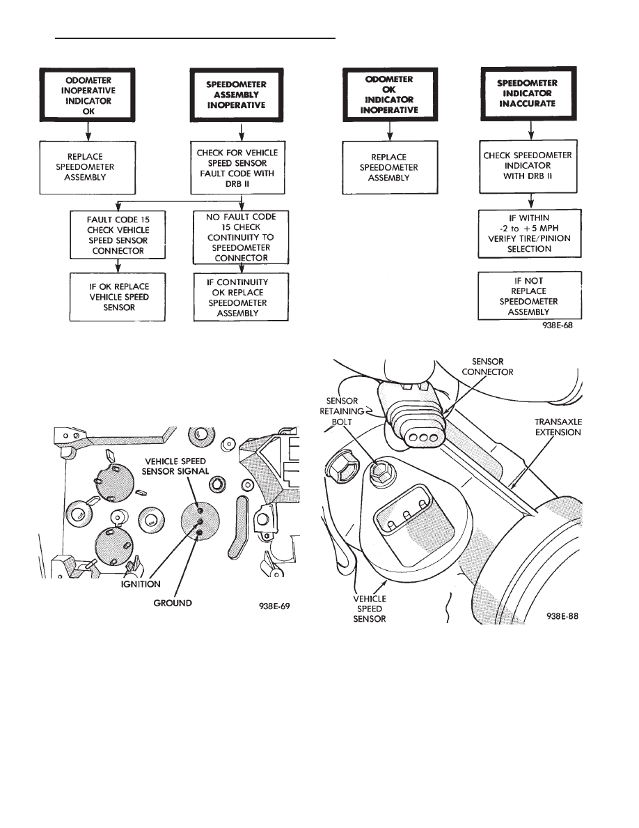
SPEEDOMETER CIRCUIT TESTING
(1) Remove speedometer from cluster.
(2) With ignition switch in the ON position, check
for battery voltage across ignition and ground pins
(Fig. 28).
(3) Check continuity from vehicle speed sensor sig-
nal pin to connector at vehicle speed sensor.
(4) Test for faulty vehicle speed sensor.
(5) If all of these tests prove good, replace speed-
ometer.
VEHICLE SPEED SENSOR REPLACEMENT
(1) Remove harness connector from sensor and
make sure weather seal is on harness connector (Fig.
29).
(2) Remove sensor retaining bolt.
(3) Pull sensor and pinion gear assembly out of
transaxle. If necessary, carefully pry loose with a flat
blade screwdriver (Fig. 30).
(4) Remove pinion gear from sensor.
(5) For installation reverse above procedures and
seat sensor assembly by hand to insure proper gear
engagement. Tighten retaining bolt to 7 N
Im (60 in.
lbs.) torque.
Fig. 27 Speedometer Diagnosis
Fig. 28 Speedometer Pins
Fig. 29 Vehicle Speed Sensor and Connector
Ä
INSTRUMENT PANEL AND GAUGES
8E - 11
Нет комментариевНе стесняйтесь поделиться с нами вашим ценным мнением.
Текст