Chrysler Le Baron, Dodge Dynasty, Plymouth Acclaim. Manual — part 298
disconnected wire at switch. The lamp also lights
when the ignition switch is turned to START.
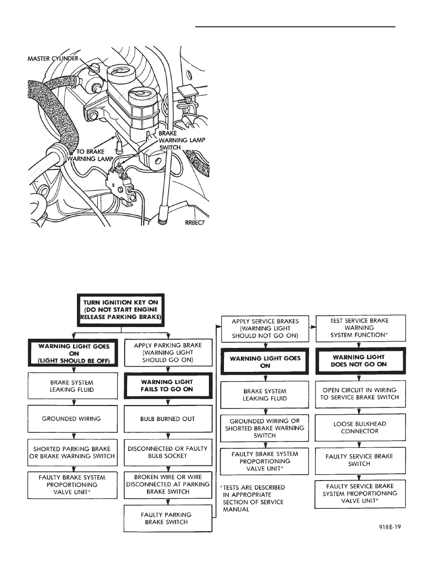
To test service brake warning system, raise vehicle
on a hoist and open a wheel cylinder bleeder while a
helper depresses brake pedal and observes warning
lamp. If lamp fails to light, inspect for a burned out
lamp, disconnected socket, a broken or disconnected
wire at switch.
If lamp is not burned out and wire continuity is
proven, replace brake warning switch in brake line
Tee fitting mounted on frame rail in engine compart-
ment below master cylinder (Fig. 8 and 9).
CAUTION: If wheel cylinder bleeder was opened
check master cylinder fluid level.
SEAT BELT WARNING SYSTEM
For testing of this system refer to Group 8M, Re-
straint Systems.
MALFUNCTION INDICATOR (CHECK ENGINE)
SYSTEM
For testing this system refer to the Powertrain Di-
agnostic Test Procedures booklet.
AIR BAG WARNING SYSTEM
For testing this system refer to Group 8M, Re-
straint Systems.
Fig. 8 Brake Warning Lamp Switch
Fig. 9 Brake System Warning Lamp Diagnosis
8E - 4
INSTRUMENT PANEL AND GAUGES
Ä

MECHANICAL/ELECTRONIC CLUSTER REMOVAL
CLUSTER BEZEL REMOVAL
(1) On column shift vehicles, place column shifter
to neutral position.
(2) On tilt steering column vehicles, adjust tilt
range to lowest position.
(3) Pull cluster bezel rearward to disengage 11
clips (Fig. 10).
(4) Remove cluster bezel.
(5) For installation reverse above procedures.
CLUSTER MASK AND LENS REMOVAL
(1) Remove cluster, radio and rear window defog-
ger bezels (Fig. 10).
(2) Remove four cluster to panel screws.
(3) Pull cluster assembly rearward. Vehicles with
column shift use care to not damage transmission
range indicator guide tube.
(4) Remove four screws holding the cluster mask to
cluster housing (Fig. 11).
(5) Pull cluster mask and lens rearward to remove.
(6) For installation reverse above procedures.
CLUSTER ASSEMBLY
REMOVAL—CLUSTER WITH TRANSMISSION RANGE
INDICATOR FROM STEERING COLUMN
(1) Disconnect battery to assure no air bag system
fault codes are stored.
(2) Remove cluster bezel (Fig. 10).
(3) On column shift vehicle: (Fig. 12 through 15).
(a) Remove lower steering column cover (Fig.
16). Release guide tube from behind fuse block.
Fig. 10 Cluster Bezel
Fig. 11 Cluster Mask and Lens
Fig. 12 Transmission Range Indicator Step 1
Fig. 13 Transmission Range Indicator Step 2
Ä
INSTRUMENT PANEL AND GAUGES
8E - 5

(b) Place gear shift lever in neutral or park.
(c) Remove guide tube from behind fuse block
and disconnect cable eyelet from column actuating
arm.
(d) Release lock bar on column insert, squeeze
legs together and remove from column (Fig. 14).
(e) Secure insert and cable guide out of the way.
(4) Remove the rear window defogger bezel and ra-
dio bezel.
(5) Remove the upper steering column cover.
(6) Remove the four screws attaching cluster hous-
ing to the base panel.
(7) Pull cluster rearward, reach behind cluster and
disconnect the two wiring harnesses.
(8) Remove cluster assembly.
INSTALLATION
(1) Connect wiring harnesses.
(2) Position cluster and secure to base panel with
four screws.
(3) On column shift vehicles (Fig. 12 through 15):
Fig. 15 Transmission Range Indicator Step 4
Fig. 16 Instrument Panel Bezels
Fig. 14 Transmission Range Indicator Step 3
8E - 6
INSTRUMENT PANEL AND GAUGES
Ä

(a) Route transmission range indicator guide as-
sembly under left steering column wing and down
left side of column (Fig. 12).
(b) Insert flange of column insert into column,
squeeze legs together with tabs under column
jacket and engage lock bar to secure insert (Fig.
14).
(c) Hook cable eyelet to steering column actuator
check pointer, should indicate neutral. Do not kink
or bind transmission range indicator guide tube
and position guide tube in original location.
(d) Adjust with tool if necessary to center pointer
on N (Neutral) and check in other gears (Fig. 15).
(4) Install upper and lower steering column cover.
(5) Install the rear window defogger bezel and ra-
dio bezel.
(6) Install cluster bezel.
(7) Reconnect battery.
REMOVAL—CLUSTER WITHOUT TRANSMISSION RANGE
INDICATOR FROM STEERING COLUMN
(1) Remove cluster bezel (Fig. 10).
(2) Remove four screws attaching cluster to base
panel.
(3) Pull cluster rearward carefully, reach behind
and disconnect the two harness connectors.
(4) Carefully rotate cluster and remove the two
transmission range indicator screws.
(5) Remove cluster assembly.
(6) For installation reverse above procedures.
(a) Do not kink guide tube when installing clus-
ter.
(b) Replace guide tube behind fuse block.
GAUGES
It is not necessary to remove instrument clus-
ter assembly from vehicle for gauge replace-
ment.
When removing gauge assemblies from cluster,
gauge must be pulled straight out, not twisted, or
damage to gauge pin may result.
MULTIPLE GAUGE MALFUNCTION
If the fuel, voltage and tachometer gauges appear
to be malfunctioning, remove the cluster assembly.
Check for good pin contact between the wire harness
and printed circuit board. If there is good contact,
check for ignition voltage at ignition cavity C of the
black connector. If there is ignition voltage, check for
continuity between the wire harness ground cavity H
of the black connector and ground. If there is conti-
nuity, replace printed circuit board.
If the temperature, oil pressure and speedometer
gauges appear to be malfunctioning remove the clus-
ter assembly. Check for a good contact between the
wire harness and the printed circuit board. If there is
good contact, check for ignition voltage at cavity J of
the red connector. If there is voltage, check for con-
tinuity at cavity H of the black connector. If there is
continuity, replace the printed circuit board.
If the temperature, fuel, voltage and speedometer
gauges appear to be malfunctioning, remove the clus-
ter assembly. Check for good pin contact between the
wire harness and the printed circuit board. If there is
good contact, check ignition voltage at cavity J of the
red connector. If there is voltage, check for continuity
at cavity H of the black connector. If there is conti-
nuity, replace the printed circuit board.
GAUGE INOPERATIVE (FIG. 17 THROUGH 23)
(1) Remove gauge in question.
Fig. 17 Fuel Gauge Pins—With Tachometer
Fig. 18 Fuel Gauge Pins—Without Tachometer
Ä
INSTRUMENT PANEL AND GAUGES
8E - 7
Нет комментариевНе стесняйтесь поделиться с нами вашим ценным мнением.
Текст