Chrysler Le Baron, Dodge Dynasty, Plymouth Acclaim. Manual — part 297
INSTRUMENT PANEL AND GAUGES
CONTENTS
page
page
AA BODY
. . . . . . . . . . . . . . . . . . . . . . . . . . . . . . 1
AC AND AY BODIES
. . . . . . . . . . . . . . . . . . . . 23
AG AND AJ BODIES
. . . . . . . . . . . . . . . . . . . . 42
AP BODY
. . . . . . . . . . . . . . . . . . . . . . . . . . . . . 58
AA BODY
INDEX
page
page
Cluster and Gauge Service and Testing
. . . . . . . . 2
Electronic Cluster
. . . . . . . . . . . . . . . . . . . . . . . . 13
Fuel Gauge—Flexible Fuel
. . . . . . . . . . . . . . . . . . 2
Gauges
. . . . . . . . . . . . . . . . . . . . . . . . . . . . . . . . . 7
General Information
. . . . . . . . . . . . . . . . . . . . . . . . 1
Instrument Panel
. . . . . . . . . . . . . . . . . . . . . . . . . 21
Interior Lamp Replacement
. . . . . . . . . . . . . . . . . 21
Mechanical/Electronic Cluster Removal
. . . . . . . . . 5
Switch and Panel Component Service
. . . . . . . . . 15
GENERAL INFORMATION
INSTRUMENT CLUSTERS
There are three instrument cluster assemblies. The
mechanical
clusters
incorporate
magnetic
type
gauges. The electronic instrument cluster incorpo-
rates, a digital speedometer/odometer and electronic
analog gauges.
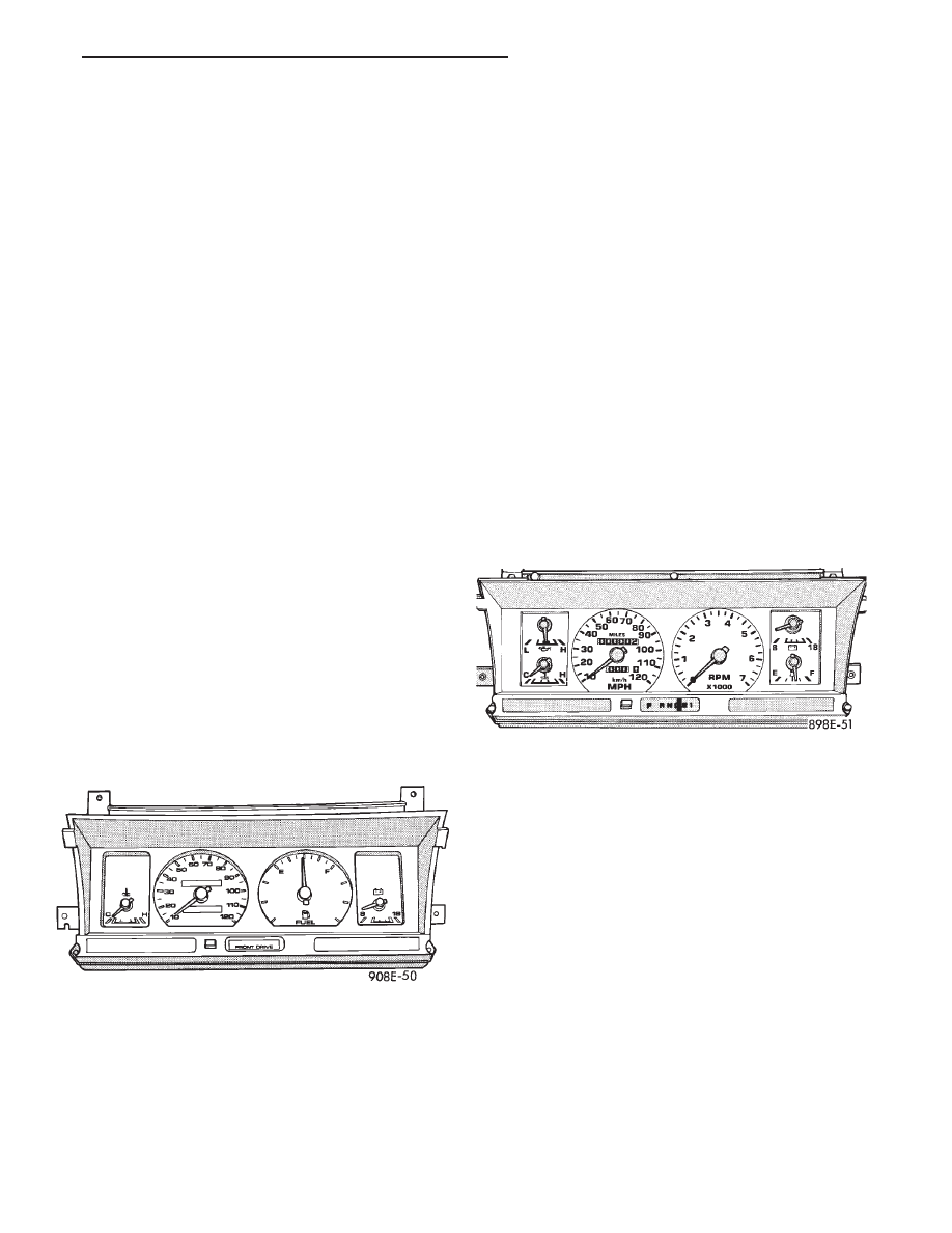
The mechanical Lo-Line instrument cluster has
magnetic type gauges for coolant temperature, fuel
level and charging system voltage (Fig. 1).
The mechanical Hi-Line instrument cluster has
magnetic type gauges for oil pressure, coolant tem-
perature, charging system voltage and fuel level. The
premium instrument cluster also has a tachometer
(Fig. 2).
If the ignition switch is in the OFF position each
gauge will show a reading, except for the volt gauge.
However the readings are only accurate when the ig-
nition switch is in the ON position.
TACHOMETER DRIVE MODULE
The tachometer drive module is an electronic mod-
ule used to drive a magnetic tachometer in a conven-
tional instrument cluster.
ELECTRONIC DIGITAL CLOCK
The electronic digital clock is in the radio. The
clock and radio each use the display panel built into
the radio. A digital readout indicates the time in
hours and minutes whenever the ignition switch is in
the ON or ACC position.
When the ignition switch is in the OFF position, or
when the radio frequency is being displayed, time
keeping is accurately maintained.
MESSAGE CENTER
The message center includes the graphic display of
the car with illuminating graphics for: low wind-
Fig. 1 Instrument Cluster
Fig. 2 Instrument Cluster With Tachometer
Ä
INSTRUMENT PANEL AND GAUGES
8E - 1
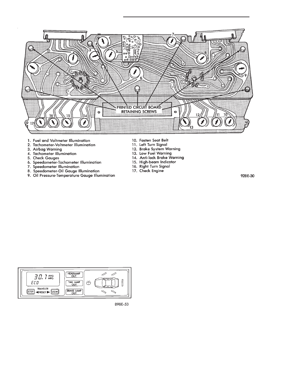
shield washer fluid, door ajar for each door, and
trunk ajar. It also includes headlamp out, tail lamp
out, and brake lamp out warning lights (Fig. 3),
these lights are operated by a lamp outage module.
When there is no message center there is no door
ajar function.
TRAVELER
The traveler is a five function trip computer. It
uses vacuum fluorescent displays to display: trip
miles, instantaneous fuel economy, trip elapsed time,
trip average fuel economy and, estimate distance to
empty. It is located in the message center (Fig. 4).
WARNING LAMPS AND INDICATOR LIGHTS
The
mechanical
instrument
cluster
assemblies
have warning lamps and indicator lights for ten dif-
ferent systems. These include left and right turn sig-
nals, low fuel level, low oil pressure, high beam
indicator, seat belt reminder, brake system, malfunc-
tion indicator (check engine) lamp, check gauges, an-
ti-lock system and air bag system indicator.
The low oil pressure indicator replaces the Check
Gauges indicator in the cluster assembly without a
tachometer.
In the cluster assembly with tachometer, Check
Gauges indictor illuminates in a warning situation.
This will notify driver to check for a problem in cool-
ant temperature, oil pressure or electrical systems.
CLUSTER AND GAUGE SERVICE AND TESTING
CAUTION: Disconnect battery cable. Before servic-
ing the instrument panel. Reconnect battery cable
when power is required for test purposes.
FUEL GAUGE—FLEXIBLE FUEL
The flexible fuel vehicle uses a dampened fuel
gauge. Methanol fuel causes erratic gauge movement
if the proper gauge is not used.
The unique fuel gauge may be identified by either
a green logo on the face of the gauge or by checking
the part number. Remove cluster from the instru-
ment panel and check the part number on top of the
cluster. Refer to Mechanical/Electronic Cluster Re-
moval for proper procedures. Refer to parts catalog
for proper part number.
Fig. 3 Message Center
Fig. 4 Traveler and Message Center
8E - 2
INSTRUMENT PANEL AND GAUGES
Ä
SENDING UNIT TEST
When a problem occurs with a cluster gauge, be-
fore disassembling the cluster to check the gauge,
check for a defective sending unit or wiring.
(1) Sending units and wiring can be checked by
grounding the connector leads, at the sending unit,
in the vehicle.
(2) With the ignition in the ON position; a
grounded input will cause the oil, fuel or tempera-
ture gauge to read at or above maximum.
LOW OIL PRESSURE/CHECK GAUGES
WARNING LAMP TEST
The low oil pressure/check gauges warning lamp
will illuminate when the ignition key is turned to
the ON position without starting the vehicle.
In the cluster assembly without tachometer, the
low oil pressure lamp will illuminate if the engine oil
pressure drops below a safe oil pressure level.
In the cluster assembly with tachometer, the Check
Gauges warning lamp illuminates when there is a
problem in oil pressure level, high engine tempera-
ture or low voltage.
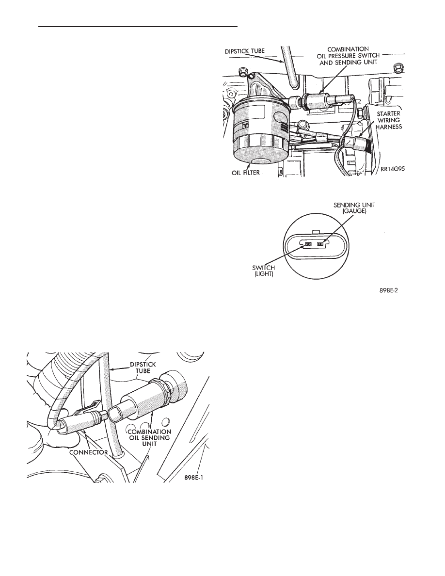
To test the system turn ignition key to the ON po-
sition. If the lamp fails to light, inspect for a broken
or disconnected wire at the oil pressure combination
unit, which is located at the front of the engine (Figs.
5 and 6). If the wire at the connector checks good,
pull connector loose from the switch terminal and
with a jumper wire ground connector to the engine
(Fig. 7). With the ignition key turned to the ON po-
sition check the warning lamp. If lamp still fails to
light, inspect for a burned out lamp or disconnected
socket in the cluster.
COMBINATION OIL UNIT TEST
The combination oil unit has two functions:
(1) The normal closed circuit keeps the oil pressure
warning/check gauges lamp on until there is oil pres-
sure (Fig. 7).
(2) The sending unit provides a resistance that
varies with oil pressure.
(3) To test the normally closed oil lamp circuit, dis-
connect the locking connector and measure the resis-
tance between the switch terminal and the metal
housing. The ohmmeter should read 0 ohms. Start
the engine.
(4) If there is oil pressure, the ohmmeter should
read an open circuit.
(5) To test the sending unit, measure the resis-
tance between the sending unit terminal and the
metal housing. The ohmmeter should read open.
Start the engine.
(6) The ohmmeter should read between 30 to 55
ohms, depending on engine speed, oil temperature,
and oil viscosity.
(7) If the above results are not obtained, replace
the switch.
BRAKE SYSTEM WARNING LAMP TEST
The brake warning lamp illuminates when parking
brake is applied with ignition key turned ON. The
same lamp will also illuminate should one of the two
service brake systems fail when brake pedal is ap-
plied. To test system turn ignition key ON, and ap-
ply parking brake. If lamp fails to light, inspect for a
burned out lamp, disconnected socket, a broken or
Fig. 5 Combination Oil Unit (2.5L)
Fig. 6 Combination Oil Unit (3.0L)
Fig. 7 Combination Oil Unit Test
Ä
INSTRUMENT PANEL AND GAUGES
8E - 3
Нет комментариевНе стесняйтесь поделиться с нами вашим ценным мнением.
Текст