Chrysler Le Baron, Dodge Dynasty, Plymouth Acclaim. Manual — part 65
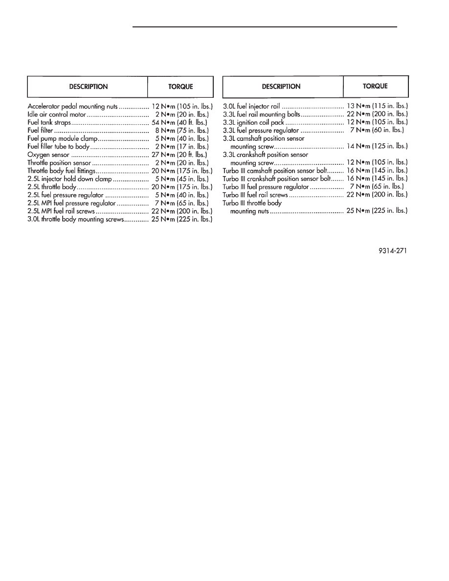
SPECIFICATIONS
TORQUE
14 - 178
FUEL SYSTEMS
Ä
STEERING
CONTENTS
page
page
ACUSTAR STANDARD AND TILT STEERING
COLUMN
. . . . . . . . . . . . . . . . . . . . . . . . . . . . 28
AUTOMATIC TRANSMISSION SHIFTER/IGNITION
INTERLOCK
. . . . . . . . . . . . . . . . . . . . . . . . . . 36
GENERAL INFORMATION . . . . . . . . . . . . . . . . . . 1
POWER STEERING GEAR
. . . . . . . . . . . . . . . . 25
POWER STEERING PUMPS
. . . . . . . . . . . . . . . . 1
SPECIFICATIONS AND TIGHTENING
REFERENCE
. . . . . . . . . . . . . . . . . . . . . . . . . . 42
GENERAL INFORMATION
Safety goggles should be worn at all times
when working on any steering gear or pump.
Throughout this group, references may be made to
a particular vehicle by letter or number designation.
A chart showing the breakdown of these designations
is included in the Introduction Section at the front of
this service manual.
The power steering system consists of these four
major components. Power Steering Pump, Power
Steering Gear, Pressure Hose, and Return Line.
Turning of the steering wheel is converted into lin-
ear travel through the meshing of the helical pinion
teeth with the rack teeth. Power assist steering is
provided by an open center, rotary type control valve.
It is used to direct oil from the power steering pump
to either side of the integral steering rack piston.
Road feel is controlled by the diameter of a torsion
bar which initially steers the vehicle. As steering ef-
fort increases as in a turn, the torsion bar twists,
causing relative rotary motion between the rotary
valve body and valve spool. This movement directs
oil behind the integral rack piston, which in turn,
builds up hydraulic pressure and assists in the turn-
ing effort.
POWER STEERING PUMPS
INDEX
page
page
Checking Power Steering Fluid Level
. . . . . . . . . . 9
Flow Control Valve Fitting O-Ring Seal
. . . . . . . . 23
General Information
. . . . . . . . . . . . . . . . . . . . . . . . 1
Power Steering Hoses
. . . . . . . . . . . . . . . . . . . . . 11
Power Steering Pressure Switch
. . . . . . . . . . . . . 10
Power Steering Pump Fluid Reservoirs
. . . . . . . . 22
Power Steering Pump Pressure Test
. . . . . . . . . . . 9
Power Steering Pump Pulley Service
. . . . . . . . . . 20
Power Steering Pump Removal
. . . . . . . . . . . . . . 12
Power Steering Pump Service
. . . . . . . . . . . . . . . . 2
Power Steering Pump—Initial Operation
. . . . . . . 24
Steering Components Service Diagnosis
. . . . . . . . 2
GENERAL INFORMATION
Hydraulic pressure for operation of the power
steering gear is provided by a belt driven power
steering pump. The power steering pump is a con-
stant flow rate and displacement, vane type pump.
Different styles of Saginaw power steering pumps are
used depending on the engine application of the ve-
hicle.
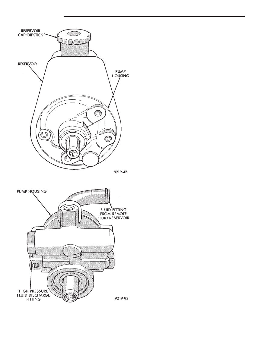
On all four cylinder and 3.0-liter V-6 applications
the Saginaw Ham Can power steering pump is used
(Fig. 1).
On the 3.3 & 3.8-liter V-6 and Turbo III applica-
tions, different versions of the Saginaw T/C style
power steering pump is used (Fig. 2). The 3.3 & 3.8
liter V-6 engine application uses the T/C style power
steering pump with a remote mounted reservoir for
the power steering fluid. On the Turbo III application
of the T/C style power steering pump, the power
steering fluid reservoir is integral to the power steer-
ing pump.
On the integral reservoir type pump (Fig. 1) the
pump housing and internal components are combined
with the reservoir to form a one-piece mechanism.
The Saginaw T/C style power steering pump (Fig.
2), consists of the power steering pump internal com-
ponents and pump housing. The Saginaw T/C style
power steering pump though has no internal reser-
voir for the power steering fluid. Depending on vehi-
Ä
STEERING
19 - 1
cle and or engine application the Saginaw T/C style
power steering pump is used on, it will be equipped
with a plastic integral or remote mounted power
steering fluid reservoir.
Drive tangs on the power steering gear pinion, mate
loosely with the stub shaft of the steering gear. This
will allow manual steering control to be maintained, if
the drive belt on the power steering pump should
break. However, under these conditions, steering effort
will significantly increase.
STEERING COMPONENTS SERVICE DIAGNOSIS
POWER STEERING PUMP SERVICE
The service procedures for the Saginaw power steer-
ing pump are limited to the areas and components
listed below. No repair procedures are to be done
on internal components of the Saginaw power
steering pumps.
• Repair of power steering fluid leaks from areas of
the power steering pump sealed by O-rings is allowed
(See Pump Leak Diagnosis). However power steering
pump shaft seal leakage will require replacement of
the pump.
• Power steering fluid reservoirs, related components
and attaching hardware.
• Power steering fluid reservoir filler cap/dipstick as-
semblies.
Because of unique shaft bearings, flow control levels
or pump displacements, power steering pumps may be
used only on specific vehicle applications. Be sure that
all power steering pumps are only replaced with a
pump that is the correct replacement for that specific
application.
Hydraulic pressure is provided for operation of the
power steering gear by the belt driven power steering
pumps (Fig. 1 & 2). It is a constant displacement, vane
type pump. The power steering pump is connected to
the steering gear by a power steering fluid pressure
hose and return hose.
Rectangular pumping vanes in the shaft driven rotor,
move power steering fluid from the intake to the cam ring
pressure cavities of the power steering pump. As the rotor
begins to turn, centrifugal force throws the vanes against
the inside surface of the cam ring to pickup residual oil.
This oil is then forced into the high pressure area. As more
oil is picked up by the vanes. That additional oil is forced
into the cavities of the thrust plate through two crossover
holes in the cam ring and pressure plate. The crossover
holes empty into the high pressure area between the
pressure plate and the housing end cover.
As the high pressure area is filled, oil flows under
the vanes in the rotor slots, forcing the vanes to follow
the inside surface of the cam ring. As the vanes
reach the restricted area of the cam ring, oil is
forced out from between the vanes. When excess oil
flow is generated during high-speed operation, a regu-
lated amount of oil returns to the pump intake side
through a flow control valve. The flow control valve
reduces the power required to drive the pump
and holds down temperature build-up.
Fig. 1 Saginaw Ham Can Power Steering Pump
Fig. 2 Saginaw T/C Style Power Steering Pump
19 - 2
STEERING
Ä
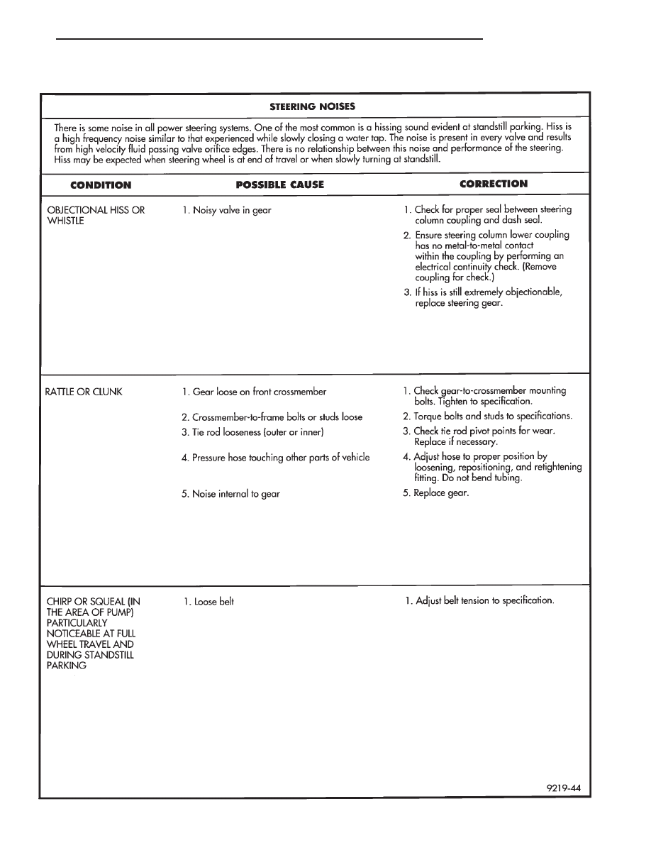
POWER STEERING SERVICE DIAGNOSIS
Ä
STEERING
19 - 3
Нет комментариевНе стесняйтесь поделиться с нами вашим ценным мнением.
Текст