Chrysler Le Baron, Dodge Dynasty, Plymouth Acclaim. Manual — part 295
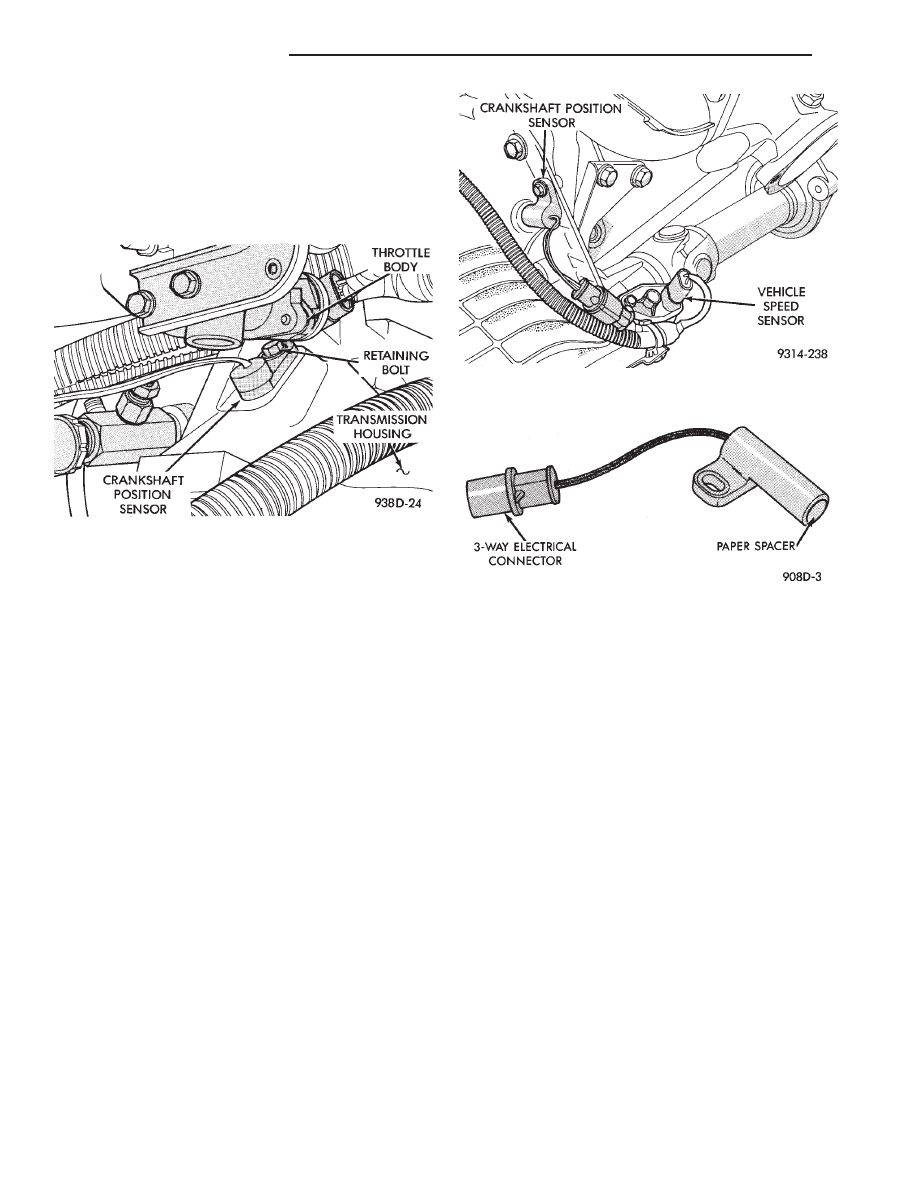
CRANKSHAFT POSITION SENSOR—TURBO III EN-
GINE
REMOVAL
(1) Remove throttle body.
(2) Remove inter-cooler to turbo-charger air hose.
(3) Disconnect crank timing sensor pick-up lead at
wiring harness connector (Fig. 7).
(4) Remove crank timing sensor retaining bolt.
(5) Pull crank timing sensor straight up out of the
transaxle housing.
INSTALLATION
(1) Install sensor in transaxle. Push sensor down
until contact is made with the transaxle housing. Hold
the sensor in this position. Install and tighten retain-
ing bolt to 16 N
Im (145 in. lbs.) torque.
(2) Connect electrical connector to sensor.
CRANKSHAFT POSITION SENSOR—3.3L AND 3.8L
ENGINES
REMOVAL
(1) Disconnect crankshaft position sensor electrical
connector from the wiring harness connector (Fig. 8).
(2) Remove sensor retaining bolt.
(3) Pull crankshaft position sensor straight up out of
the transaxle housing.
INSTALLATION
If installing the original sensor, clean off the
old spacer on the sensor face. A NEW SPACER
must be attached to the sensor face before instal-
lation. If the sensor is being replaced, confirm
that the paper spacer is attached to the face of
the new sensor (Fig. 9).
(1) Install sensor in transaxle and push sensor down
until contact is made with the drive plate. While
holding the sensor in this position, and install and
tighten the retaining bolt to 12 N
Im (105 in. lbs.)
torque.
(2) Connect crankshaft position sensor electrical
connector to the wiring harness connector.
CAMSHAFT POSITION SENSOR SERVICE—TURBO
III ENGINE
REMOVAL
(1) Disconnect camshaft position sensor connector
from wiring harness (Fig. 10).
(2) Remove camshaft position sensor retaining bolt
and remove sensor.
INSTALLATION
If installing the original sensor, clean off the
old spacer on the sensor face. A NEW SPACER
must be attached to the face before installation.
If the sensor is being replaced, confirm that the paper
spacer is attached to the face (Fig. 11).
(1) Install sensor in the cylinder head and push
sensor down until contact is made with the camshaft
gear. While holding the sensor in this position, install
and tighten the retaining bolt 16 N
Im (145 in. lbs.)
torque.
(2) Connect electrical connector to the sensor.
Fig. 7 Crankshaft Position Sensor Service—Turbo III
Engine
Fig. 8 Crankshaft Position Sensor—3.3L and 3.8L
Engines
Fig. 9 Crankshaft Position Sensor and Spacer
8D - 42
IGNITION SYSTEMS
Ä
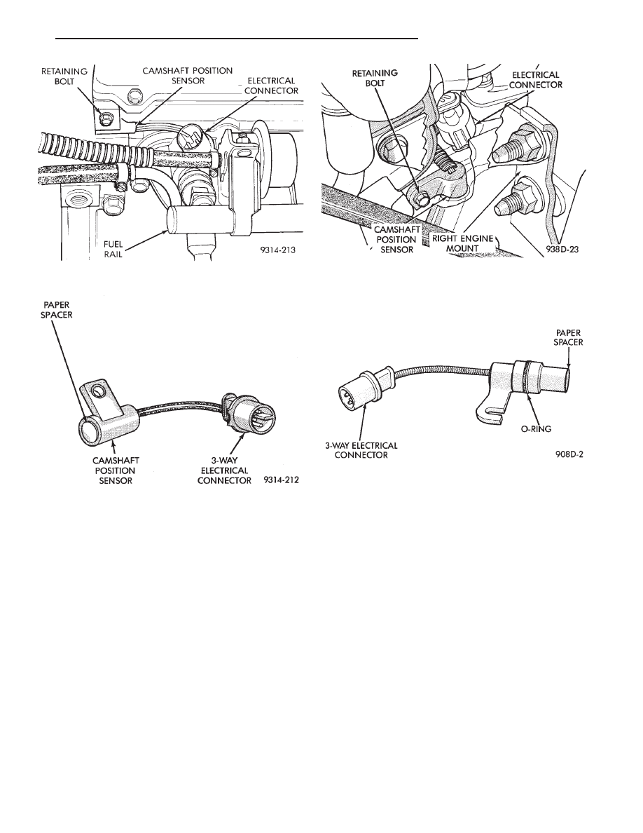
CAMSHAFT POSITION SENSOR—3.3L AND 3.8L
ENGINES
REMOVAL
(1) Disconnect camshaft position sensor electrical
connector from the wiring harness (Fig. 12).
(2) Remove engine mount support bracket.
(3) Loosen camshaft position sensor retaining bolt
enough to allow slot in sensor to slide past the bolt.
(4) Pull sensor up out of the chain case cover. Do not
pull on the sensor lead. There is an O-ring on the
sensor case. The O-ring may make removal difficult. A
light tap to top of sensor prior to removal may reduce
force needed for removal.
INSTALLATION
If installing the original sensor, clean off the
old spacer on the sensor face. A NEW SPACER
must be attached to the face before installation.
Inspect O-ring for damage, replace if necessary. If the
sensor is being replaced, confirm that the paper
spacer is attached to the face and O-ring is posi-
tioned in groove of the new sensor (Fig. 13).
(1) Apply a couple drops of clean engine oil to the
O-ring prior to installation. Install sensor in the
chain case cover and push sensor down until contact
is made with the camshaft timing gear. While hold-
ing the sensor in this position, install and tighten
the retaining bolt 14 N
Im (125 in. lbs.) torque.
(2) Connect camshaft position sensor electrical con-
nector to harness connector. Position connector away
from the accessory belt.
(3) Install engine mount support bracket.
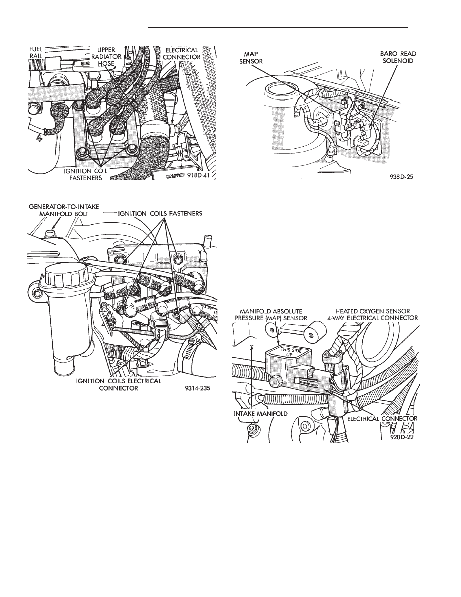
IGNITION COIL SERVICE—TURBO III ENGINE
(1) Remove spark plug cables from coil (Fig. 14).
(2) Remove electrical connector from coil pack.
(3) Remove ignition coil fasteners.
(4) Reverse the above procedure for installation.
Tighten fasteners to 12 N
Im (105 in. lbs.) torque.
IGNITION COIL—3.3L AND 3.8L ENGINE
(1) Remove spark plug cables from coil (Fig. 15).
(2) Remove ignition coil electrical connector.
(3) Remove ignition coil mounting screws.
(4) Remove ignition coil.
Fig. 12 Camshaft Position Sensor Location—3.3L
and 3.8L Engine
Fig. 13 Camshaft Position Sensor—3.3L and 3.8L
Engines
Fig. 10 Camshaft Position Sensor Location—Turbo
III Engines
Fig. 11 Camshaft Position Sensor—Turbo III Engine
Ä
IGNITION SYSTEMS
8D - 43
Reverse
the
above
procedure
for
installation.
Tighten mounting screws to 12 N
Im (105 in. lbs.)
torque.
MANIFOLD ABSOLUTE PRESSURE (MAP)
SENSOR—TURBO III ENGINE
The map sensor mounts to the right front fender
(Fig. 16).
(1) Remove vacuum hose from MAP sensor.
(2) Remove MAP sensor mounting screws.
(3) Remove electrical connector from sensor.
(4) Reverse procedure for installation.
MANIFOLD ABSOLUTE PRESSURE (MAP)
SENSOR—3.3L AND 3.8L ENGINES
The alignment of the MAP sensor is critical to the
sensors performance. The top of the sensor is marked
This Side Up (Fig. 17).
(1) Disconnect electrical connector from MAP sen-
sor.
(2) Remove sensor by unscrewing from the intake
manifold (Fig. 17).
(3) Reverse the above procedure for installation.
Fig. 14 Ignition Coil Service—2.2L Turbo III
Fig. 15 Ignition Coil Removal and Installation
Fig. 16 MAP Sensor—Turbo III Engine
Fig. 17 Manifold Absolute Pressure Sensor
8D - 44
IGNITION SYSTEMS
Ä
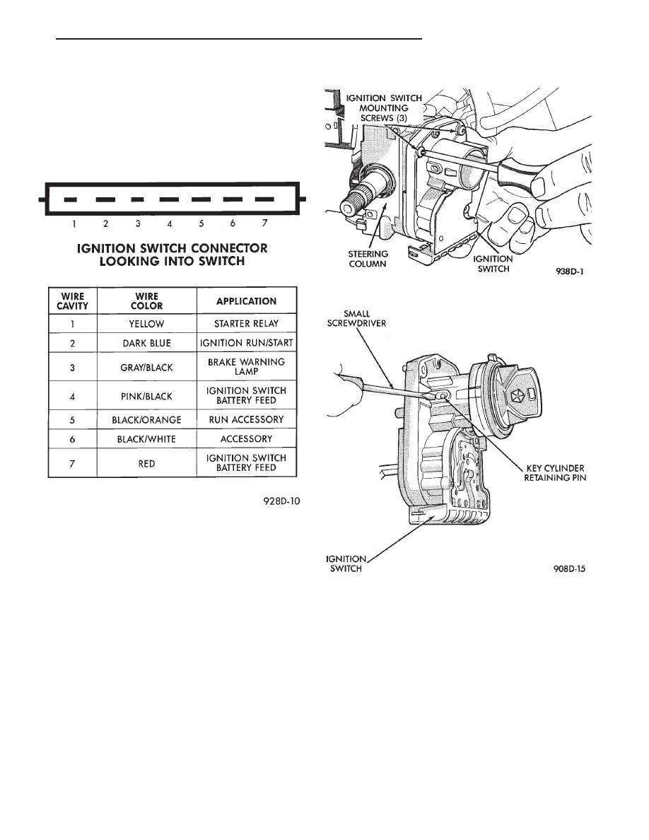
IGNITION SWITCH
IGNITION SWITCH AND KEY CYLINDER SERVICE
The ignition switch is located on the steering col-
umn. The Key In Switch is located in the ignition
switch module. For diagnosis of the Key In Switch,
refer to Section 8M.
REMOVAL
If the vehicle has a floor mounted gear shifter,
place the selector in the Park position.
(1) Disconnect negative cable from battery.
(2) If the vehicle has a tilt column, remove the tilt
lever by turning it counterclockwise.
(3) Remove upper and lower covers from steering
column.
(4) Remove ignition switch mounting screws. Use
tamper proof torx bit Snap-on TTXR15A2, TTXR20A2
or equivalent to remove the screws (Fig. 1).
(5) Gently pull switch away from the column. Release
connector locks on the 7 terminal wiring connector,
then remove the connector from the ignition switch.
(6) Release connector lock on the 4 terminal con-
nector, then remove the connector from the ignition
switch.
(7) To remove the key cylinder from the ignition
switch:
(a) Insert key in the ignition switch. Turn the
key to the LOCK position. Using a small screw-
driver, depress the key cylinder retaining pin until
it is flush with the key cylinder surface (Fig. 2).
(b) Rotate the key clockwise to the OFF position.
The key cylinder will unseat from the ignition
switch (Fig. 3). When the key cylinder is unseated,
it will be approximately 1/8 inch away from the ig-
nition switch halo light ring. Do not attempt to
remove the key cylinder at this time.
(c) With the key cylinder in the unseated posi-
tion, rotate the key counterclockwise to the lock po-
sition and remove the key.
(d) Remove key cylinder from ignition switch
(Fig. 4).
INSTALLATION
If the vehicle has a floor mounted gear shifter,
place the selector in the Park position.
IGNITION SWITCH DESIGNATIONS
Fig. 1 Ignition Switch Screw Removal
Fig. 2 Key Cylinder Retaining Pin
Ä
IGNITION SYSTEMS
8D - 45
Нет комментариевНе стесняйтесь поделиться с нами вашим ценным мнением.
Текст