Chrysler Le Baron, Dodge Dynasty, Plymouth Acclaim. Manual — part 296
(1) Connect electrical connectors to the ignition
switch. Make sure that the switch locking tabs are fully
seated in the wiring connectors.
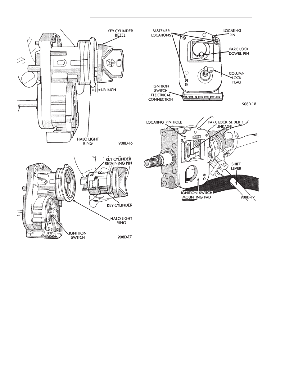
(2) Before attaching the ignition switch to a tilt
steering column, the transaxle shifter must be in the
Park position. Also the park lock dowel pin and the
column lock flag must be properly indexed before
installing the switch (Fig. 5).
(a) Place the transaxle shifter in the PARK posi-
tion.
(b) Place the ignition switch in the lock position.
The switch is in the lock position when the column
lock flag is parallel to the ignition switch terminals
(Fig. 5).
(c) Position ignition switch park lock dowel pin so
it will engage the steering column park lock slider
linkage (Fig. 6).
(d) Apply a light coating of grease to the column
lock flag and the park lock dowel pin.
(3) Place the ignition switch against the lock hous-
ing opening on the steering column. Ensure ignition
switch park lock dowel pin enters the slot in the park
lock slider linkage in the steering column.
(4) Install ignition switch mounting screws. Tighten
screws to 2 N
Im (17 in. lbs.) torque.
(5) Install steering column covers. Tighten screws to
2 N
Im (17 in. lbs.) torque.
(6) If the vehicle is equipped with a tilt steering
column, install the tilt lever.
(7) To install the ignition key in the lock cylinder:
(a) With the key cylinder and the ignition switch
in the Lock position, insert the key cylinder into the
ignition switch until it bottoms.
(b) Insert ignition key into lock cylinder. While
gently pushing the key cylinder in toward the igni-
tion switch, rotate the ignition key until to the end of
travel.
(c) Connect negative cable to battery.
(8) Check for proper operation of the halo light, shift
lock (if applicable), and column lock. Also check for
proper operation of the ignition switch accessory, lock,
off, run, and start positions.
Fig. 3 Unseated Key Cylinder
Fig. 4 Key Cylinder Removal
Fig. 5 Ignition Switch View From Column
Fig. 6 Ignition Switch Mounting Pad
8D - 46
IGNITION SYSTEMS
Ä
SPECIFICATIONS
GENERAL INFORMATION
The following specifications are published from the
latest information available at the time of publica-
tion. If anything differs from the specifications on the
Vehicle Emission Control Information Label, use the
specifications on the label.
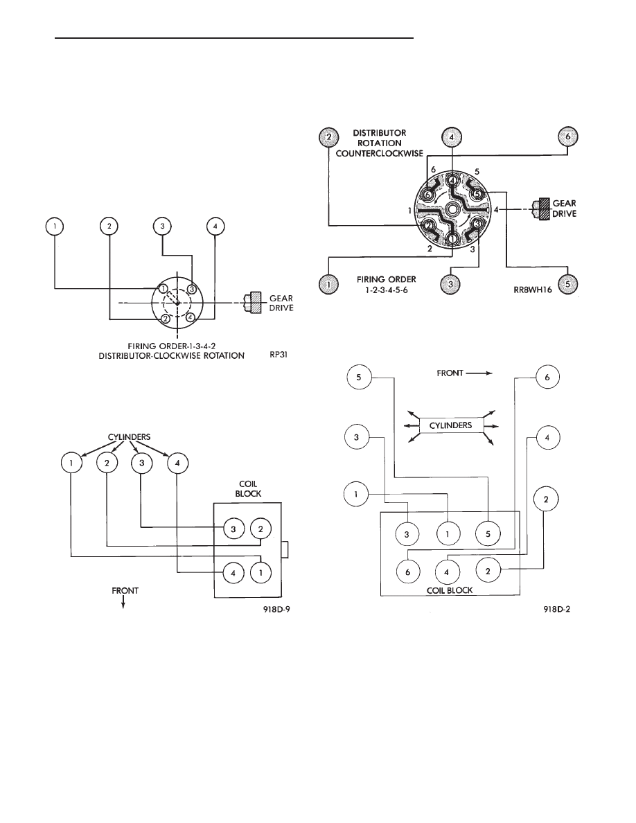
SPARK PLUG WIRE ROUTING—2.2L TBI, 2.5L
TBI AND 2.5L MPI ENGINES
SPARK PLUG WIRE ROUTING—
TURBO III ENGINE
SPARK PLUG WIRE ROUTING—3.0L ENGINE
SPARK PLUG WIRE ROUTING—3.3L AND
3.8L ENGINES
Ä
IGNITION SYSTEMS
8D - 47
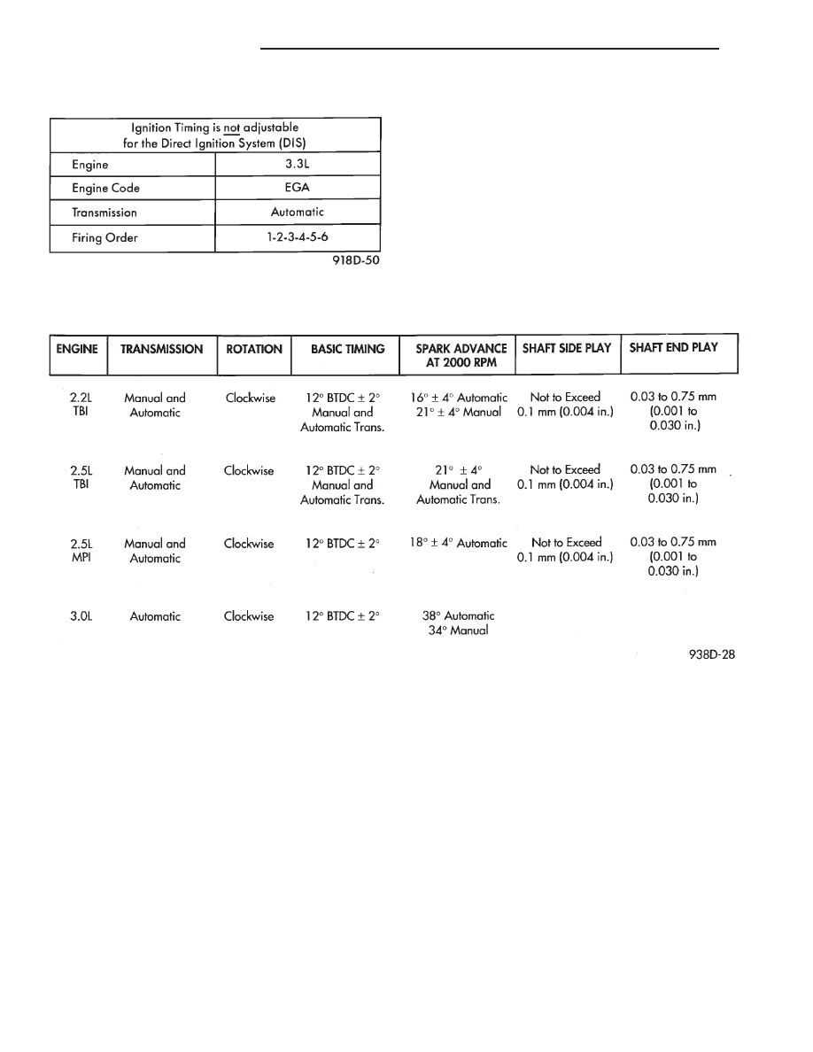
3.3L/3.8L ENGINE DIRECT IGNITION SYSTEM
DISTRIBUTORS
8D - 48
IGNITION SYSTEMS
Ä
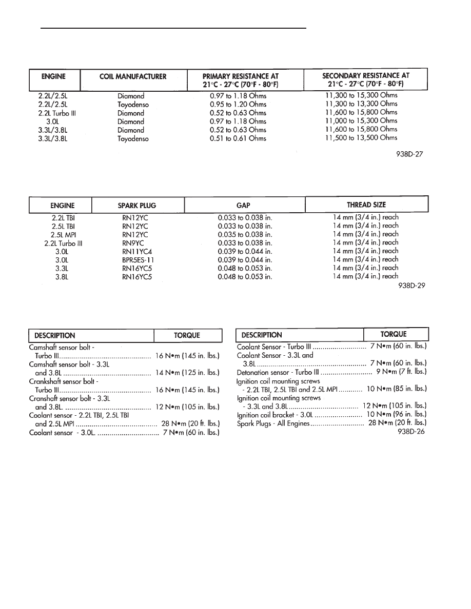
IGNITION COILS
SPARK PLUGS
TORQUE
Ä
IGNITION SYSTEMS
8D - 49
Нет комментариевНе стесняйтесь поделиться с нами вашим ценным мнением.
Текст