Chrysler Le Baron, Dodge Dynasty, Plymouth Acclaim. Manual — part 159
(7) Pull front reading lamp downward to disengage
from retaining ring in head lining and disconnect
wire connector. Remove screws holding retaining
ring to roof header.
(8) Remove pinch welt holding headlining to sun
roof opening, if equipped.
(9) Remove inside rear view mirror from wind-
shield bracket, if necessary.
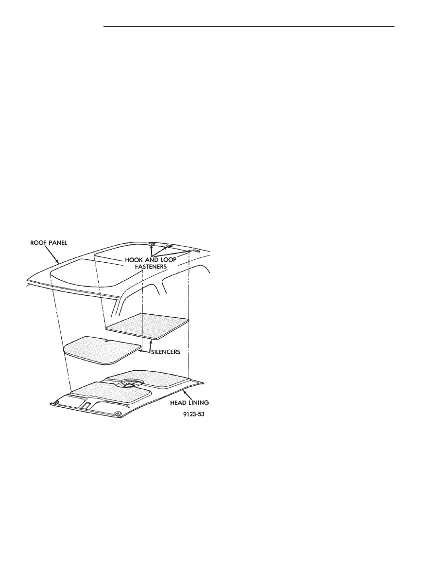
(10) Disengage hook and loop fasteners holding
head lining to roof above rear window and slide head
lining forward about 25 mm (1 in.).
(11) Shift the front of head lining to one side to
pull head lining from behind B-pillar trim. Pull head
lining from behind other B-pillar trim.
(12) Allow front of head lining to drop downward.
Slide head lining forward from behind quarter panel
trim.
(13) Remove head lining from vehicle.
INSTALLATION
Reverse the preceding operation.
COWL PANEL TRIM AND SCUFF PLATES
COWL PANEL AND DOOR OPENING SCUFF
PLATE REMOVAL (FIG. 22)
(1) Open front door.
(2) Remove screw holding trim panel to cowl for-
ward of the front door opening.
(3) Remove screws holding scuff plate to door sill.
(4) Separate cowl panel trim and scuff plate from
vehicle.
COWL PANEL AND DOOR OPENING SCUFF
PLATE INSTALLATION
Reverse the preceding operation.
REAR DOOR OPENING SCUFF PLATE
REMOVAL (FIG. 22)
(1) Open rear door.
(2) Remove screws holding scuff plate to door sill.
(3) Separate scuff plate from vehicle.
REAR DOOR OPENING SCUFF PLATE
INSTALLATION
Reverse the preceding operation.
A-PILLAR AND ROOF RAIL MOULDINGS
A-PILLAR MOULDING REMOVAL (FIG. 22)
(1) Open front door.
(2) Disengage clips holding A-pillar moulding to
roof rail above door opening.
(3) Slide A-pillar moulding upward and pull rear-
ward to separate moulding from A-pillar.
A-PILLAR MOULDING INSTALLATION
Reverse the preceding operation.
REAR DOOR ROOF RAIL MOULDING
REMOVAL (FIG. 22)
(1) Open rear door.
(2) Disengage clips holding roof rail moulding to
roof rail above rear door opening.
(3) Separate moulding from vehicle.
REAR DOOR ROOF RAIL MOULDING
INSTALLATION
Reverse the preceding operation.
B-PILLAR TRIM PANEL
REMOVAL (FIG. 22)
(1) Remove roof rail mouldings and scuff plates as
necessary.
(2) Remove shoulder harness turning loop cover.
Remove bolt holding turning loop to B-pillar.
(3) Remove bolt holding seat belt to floor below
B-pillar.
(4) Remove upper B-pillar trim.
(5) Remove lower B-pillar trim.
INSTALLATION
Reverse the preceding operation.
QUARTER TRIM PANEL
REMOVAL (FIG. 22)
(1) Remove rear roof rail mouldings and scuff
plates as necessary.
Fig. 21 Head Lining—Typical
23 - 46
AC-BODY
Ä
(2) Remove rear shoulder harness turning loop
cover. Remove bolt holding turning loop to quarter
panel.
(3) Remove rear seat cushion and back.
(4) Remove push-in fastener holding quarter trim
to roof rail.
(5) Remove screws holding quarter trim panel to
wheelhouse kickup.
(6) Pull trim panel away from C-pillar and sepa-
rate from vehicle.
INSTALLATION
Reverse the preceding operation.
REAR SHELF TRIM PANEL
REMOVAL (FIG. 22)
(1) Remove one quarter trim panel.
(2) Remove center high mounted stop lamp cover.
Refer to Group 8L, Lamps for instructions.
(3) Disengage fasteners holding trim to shelf panel
and separate trim from vehicle.
INSTALLATION
Reverse the preceding operation.
FRONT SEAT BELTS
OUTBOARD SHOULDER HARNESS/LAP BELT
REMOVAL (FIG. 23)
(1) Remove B-pillar trim panel.
(2) Remove bolt holding seat belt retractor to
B-pillar.
(3) Separate retractor from vehicle.
OUTBOARD SHOULDER HARNESS/LAP BELT
INSTALLATION
Reverse the preceding operation.
INBOARD BUCKLE/CENTER OCCUPANT
BELTS REMOVAL (FIG. 23)
Vehicles equipped with front bucket seats with cen-
ter console do not have center occupant belts.
(1) Remove bolt holding inboard buckle/center oc-
cupant belt to floor.
(2) Disconnect seat belt sensor wire connector.
(3) Separate buckle/belt assembly from vehicle.
INBOARD BUCKLE/CENTER OCCUPANT BELT
INSTALLATION
Reverse the preceding operation.
REAR SEAT BELTS
OUTBOARD SHOULDER HARNESS/LAP BELT
REMOVAL (FIG. 24)
(1) Remove quarter trim panel.
(2) Remove bolt holding lap belt to floor at wheel-
house kickup.
(3) Remove bolt holding turning loop to inner
quarter panel.
(4) Remove bolt holding seat belt retractor to quar-
ter panel.
OUTBOARD SHOULDER HARNESS/LAP BELT
INSTALLATION
Reverse the preceding operation.
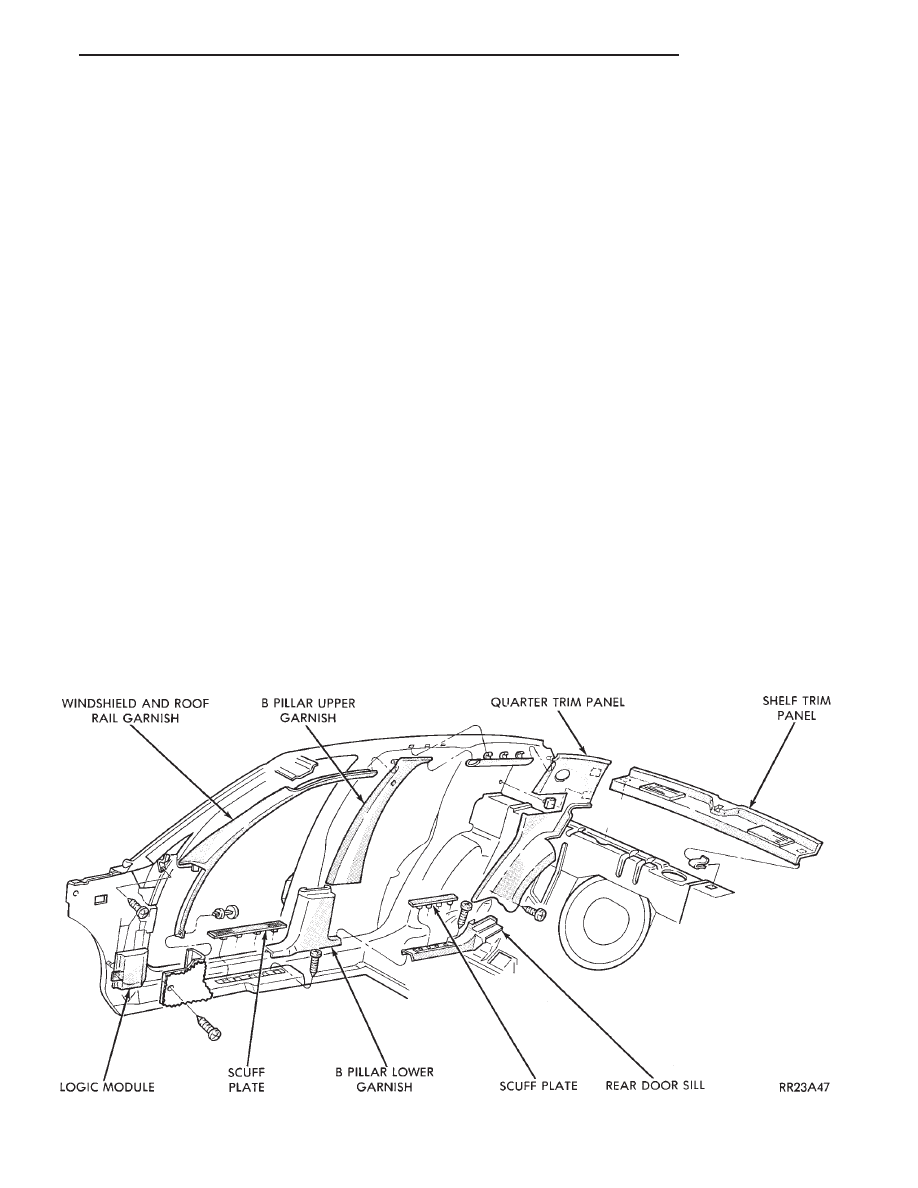
Fig. 22 Interior Mouldings, Panels, and Trim Covers
Ä
AC-BODY
23 - 47
INBOARD BUCKLE/CENTER OCCUPANT
BELTS REMOVAL (FIG. 24)
(1) Remove rear seat cushion.
(2) Remove bolt holding inboard buckle/center oc-
cupant belt to floor.
(3) Separate buckle/belt assembly from vehicle.
INBOARD BUCKLE/CENTER OCCUPANT BELT
INSTALLATION
Reverse the preceding operation.
FRONT SEATS
REMOVAL (FIG. 25 OR 26)
(1) Position seat full forward.
(2) Remove screws holding rear track riser covers
and separate covers from tracks.
(3) On power seat track, remove outboard track
cover.
(4) Remove inboard seat belt attaching bolt from
floor.
(5) Remove nuts holding seat track to floor.
(6) Position seat full rearward.
(7) Remove door sill scuff plate and disconnect
power seat track wire connector.
(8) Remove bolts holding seat track to cross mem-
ber.
(9) Remove seat from vehicle.
INSTALLATION
Reverse the preceding operation.
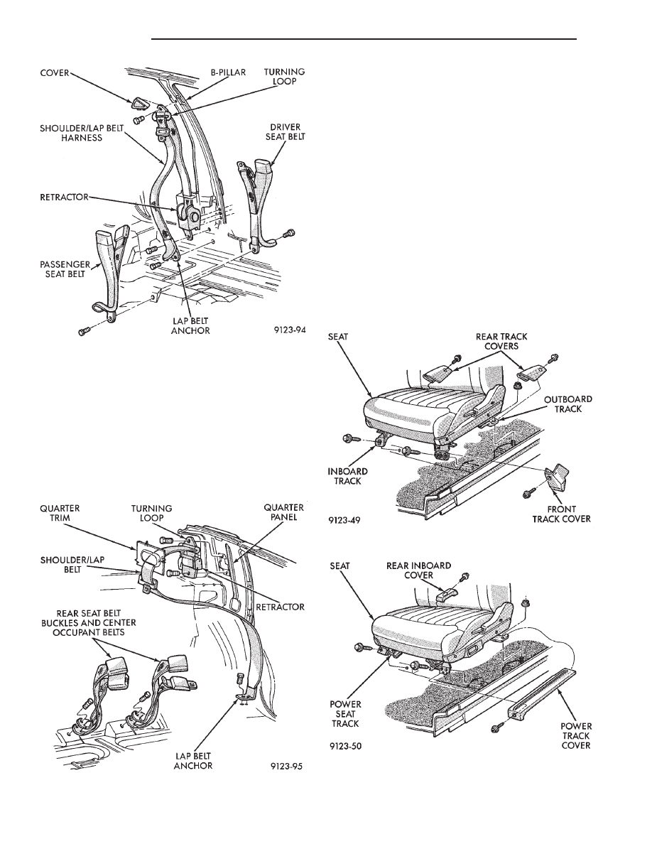
Fig. 23 Front Seat Belts
Fig. 24 Rear Seat Belts
Fig. 25 Manual Front Seat—Typical
Fig. 26 Power Front Seat—Typical
23 - 48
AC-BODY
Ä
REAR SEATS
REAR SEAT CUSHION REMOVAL
(1) Remove bolts holding cushion to floor.
(2) Disconnect center occupant seat belts from
cushion.
(3) Remove cushion from vehicle.
REAR SEAT CUSHION INSTALLATION
Reverse the preceding operation.
REAR SEAT BACK REMOVAL
(1) Remove rear seat cushion assembly.
(2) Remove bolts holding seat back to rear floor
kick-up.
(3) Lift seat back upward to disengage upper hooks
from shelf support panel.
(4) Separate seat back from vehicle.
REAR SEAT BACK INSTALLATION
Reverse the preceding operation.
BODY MOULDINGS
STICK-ON BODY SIDE MOULDING REMOVAL
AND INSTALLATION
(1) Warm the effected stick-on moulding and body
metal to approximately 38°C (100°F) using a suitable
heat lamp or heat gun.
(2) Pull stick-on moulding from painted surface.
(3) Remove adhesive tape residue from painted
surface of vehicle.
(4) If moulding is to be reused, Remove tape resi-
due from moulding. Clean back of moulding with Mo-
par
t, Super Kleen solvent or equivalent. Wipe
moulding dry with lint free cloth. Apply new body
side moulding (two sided adhesive) tape to back of
moulding.
(5) Clean body surface with Super Kleen solvent or
equivalent. Wipe surface dry with lint free cloth.
(6) Apply a length of masking tape on the body,
parallel to the top edge of the moulding to use as a
guide, if necessary.
(7) Remove protective cover from tape on back of
moulding. Apply moulding to body below the mask-
ing tape guide.
(8) Remove masking tape guide and heat body and
moulding, see step one. Firmly press moulding to
body surface to assure adhesion.
FRONT WHEEL OPENING MOULDING
REMOVAL
(1) Remove screws holding wheel opening mould-
ing to front fender.
(2) Separate moulding from fender.
FRONT WHEEL OPENING MOULDING
INSTALLATION
(1) Position moulding in wheel opening and start
top center screw of wheel opening moulding.
(2) Install screws around wheel opening.
REAR WHEEL OPENING MOULDING REMOVAL
(1) Remove screws holding wheel opening mould-
ing to quarter panel.
(2) Separate wheel opening moulding from quarter
panel.
REAR WHEEL OPENING MOULDING
INSTALLATION
(1) Position moulding in wheel opening and start
top center screw of wheel opening moulding.
(2) Install screws around wheel opening.
VINYL ROOF BONNET
REMOVAL (FIG. 27)
(1) Remove quarter panel trim covers.
(2) Remove head lining.
(3) Remove nuts holding transverse roof moulding
to roof panel and separate moulding from vehicle.
(4) Remove nuts holding vinyl top bonnet to roof.
(5) Remove rear deck filler panel.
(6) Remove screws holding rear window opening
lower valance to body.
(7) Disengage hook and loop fasteners holding vi-
nyl top bonnet to quarter panel.
(8) Pull vinyl top bonnet away from top panel to
separate bonnet from anti-flutter sealer holding bon-
net to roof.
INSTALLATION
(1) Clean anti-flutter sealer from roof surface and
inside of vinyl roof bonnet.
(2) Apply a 20 mm (0.75 in.) bead of anti-flutter
sealer across the roof panel at the mid point between
the front of the bonnet and rear of roof.
(3) Apply a 20 mm (0.75 in.) by 150 mm (6 in.)
bead of anti-flutter sealer down each roof side panel
at mid point between the door opening and rear of
roof.
(4) Place the bonnet into position on the roof panel
and align to proper fit.
(5) Reverse the removal operation.
REAR DECK FILLER PANEL
REMOVAL (FIG. 28)
(1) Raise truck lid to full up position.
(2) Remove screws holding rear deck filler panel to
body in the front trunk opening gutter.
(3) Close trunk lid, do not latch.
(4) Lift filler panel upward and separate from ve-
hicle.
Ä
AC-BODY
23 - 49
Нет комментариевНе стесняйтесь поделиться с нами вашим ценным мнением.
Текст