Chrysler Le Baron, Dodge Dynasty, Plymouth Acclaim. Manual — part 160
INSTALLATION
Reverse the preceding operation.
REAR WINDOW GLASS
REMOVAL (FIG. 29)
The rear window moulding often cannot be sal-
vaged after removal operation is completed. Verify
moulding availability from the parts supplier before
removing moulding.
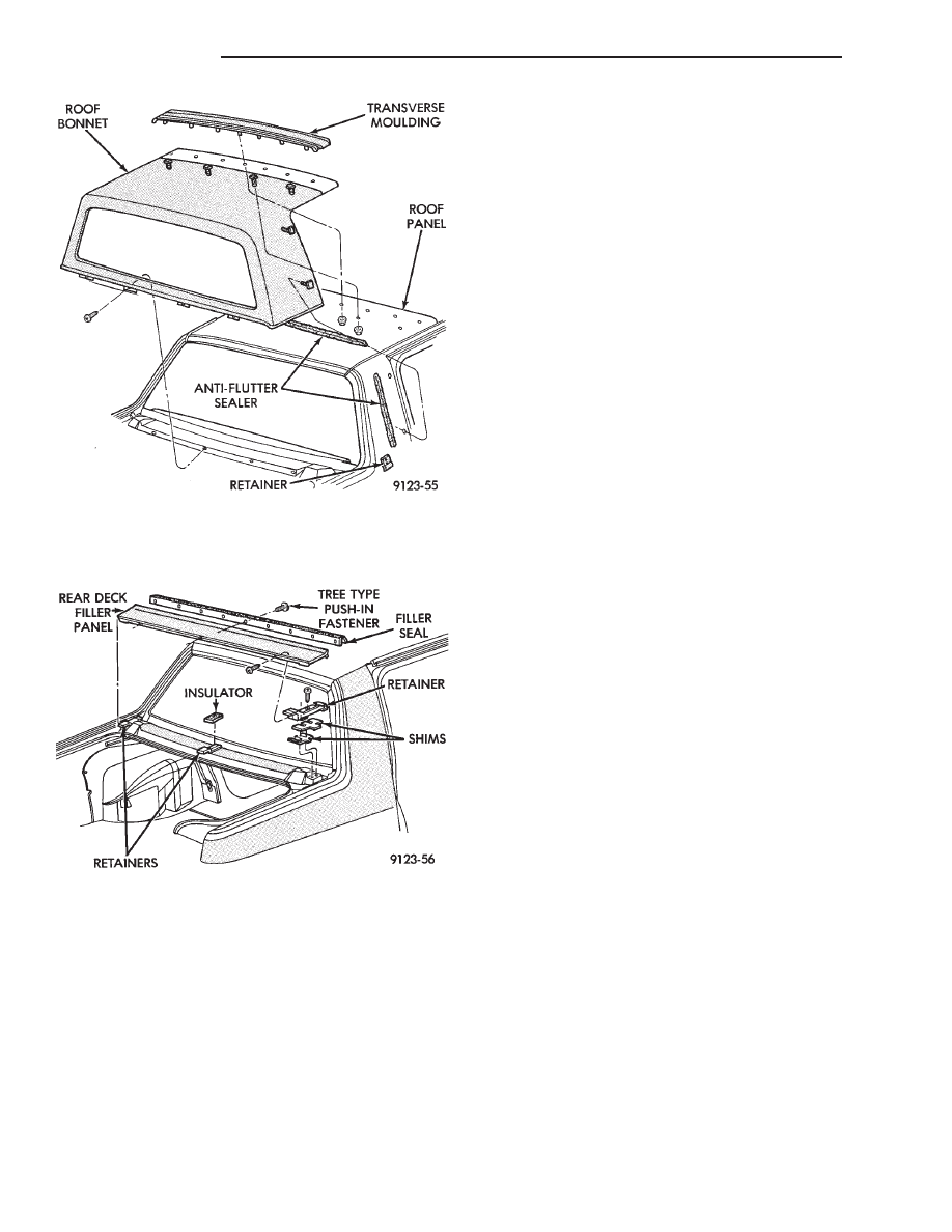
(1) Remove rear deck filler panel.
(2) Pull rear window moulding from between glass
and roof panel.
(3) Remove interior trim as necessary to gain ac-
cess to rear window defogger wire connector and
ground screw, if equipped.
(4) Remove vinyl roof bonnet, if equipped.
WARNING: WEAR EYE AND HAND PROTECTION
WHEN HANDLING SAFETY GLASS. PERSONAL IN-
JURY CAN RESULT.
CAUTION: Do not damage body or trim finish when
cutting out glass or applying fence primer.
(5) Cut the urethane around the perimeter of the
back window glass. Refer to Windshield section of
this group for proper procedures.
(6) Separate the rear window from the vehicle.
INSTALLATION
(1) Prepare the work area, window fence, and glass
the same way as described in the Windshield section
of this group.
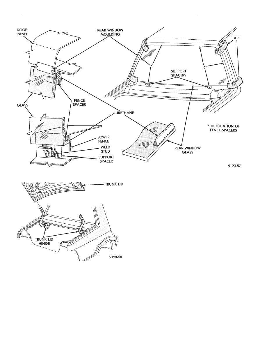
(2) Place fence spacers at the locations shown (Fig.
29).
(3) Apply a 10 mm (0.4 in.) bead of urethane
around the perimeter of the glass.
(4) Install the glass in the same manner described
in the Windshield section of this group.
(5) Install the rear window moulding in the gap
between the glass and the roof panel.
(6) Secure moulding and glass in position with
suitable tape. Remove tape after urethane has cured.
(7) Connect rear window defogger wiring. Install
interior trim and rear deck filler panel.
(8) After urethane has cured, water test rear win-
dow to verify repair. Verify rear window defogger op-
eration, see Group 8N, Rear Window Defogger.
TRUNK LID
REMOVAL (FIG. 30)
(1) Raise trunk lid to full up position.
(2) Disconnect the trunk lamp wire connector.
(3) Mark all bolt and hinge attachment locations
with a grease pencil or other suitable device to pro-
vide reference marks for installation. When install-
ing trunk lid, align all marks and secure bolts. The
trunk lid should be aligned to 4 mm (0.160 in.) gap
to the quarter panels and flush across the top sur-
faces along quarter panels.
(4) Remove the top trunk lid to hinge attaching
bolts and loosen the bottom bolts until they can be
removed by hand.
(5) With assistance of a helper at the opposite side
of the vehicle to support the trunk lid, remove the
bottom trunk lid to hinge attaching bolts. Separate
the trunk lid from the vehicle.
INSTALLATION
Reverse the preceding operation.
Fig. 27 Vinyl Roof Bonnet—Typical
Fig. 28 Rear Deck Filler Panel—Typical
23 - 50
AC-BODY
Ä
TRUNK LID HINGE
REMOVAL
(1) Remove rear deck filler panel.
(2) Disconnect trunk lid lift torsion bars from
hinges.
(3) Mark all attaching bolt, nut, and component lo-
cations with a suitable marking device. Use marks
as a reference when installing hinge.
(4) Remove bolts holding trunk lid to hinge.
(5) Remove nuts and bolts holding hinge to closure
panel below rear window glass.
(6) Separate hinge from vehicle.
INSTALLATION
Reverse the preceding operation.
TRUNK LID TORSION BAR
REMOVAL
(1) Raise and support trunk lid in the full up posi-
tion.
(2) Remove trunk lining as necessary to gain ac-
cess to torsion bars.
(3) Disengage adjusting end torsion bar from the
slot in the tension adjustment bracket.
(4) Pivot torsion bar out of lift arm swivel.
(5) Disconnect torsion bar from hinge.
INSTALLATION
Reverse the preceding operation.
Fig. 29 Rear Window Glass—Typical
Fig. 30 Trunk Lid
Ä
AC-BODY
23 - 51
AG-VEHICLE BODY COMPONENT SERVICE
INDEX
page
page
A-Pillar and Roof Rail Mouldings
. . . . . . . . . . . . . . . . . . . . . . . 60
. . . . . . . . . . . . . . . . . . . . . . 60
. . . . . . . . . . . . . . . . . 52
. . . . . . . . . . . . . . . . . . . . . . . . . . . . . 54
. . . . . . . . . . . . . . . . . . . . . . . . . . . . . 58
. . . . . . . . . . . . . . . 59
. . . . . . . . . . . . . . . . . . . . . . . . . . . . . 57
. . . . . . . . . . . . . . . . . 61
. . . . . . . . . . . . . . . . 60
. . . . . . . . . . . . . . . . . . . . . . . . . 56
. . . . . . . . . . . . . . . . . . . . . . . . . . . . 64
. . . . . . . . . . . . . . . . . . . . . 64
. . . . . . . . . . . . . . . . . . . . . 56
Front Door Silencer and Water Shield
. . . . . . . . . . . . . . . . . . 54
. . . . . . . . . . . . . . . . . . . . . . . . . . . . 55
. . . . . . . . . . . . . . . . . . . . . . . . . 61
. . . . . . . . . . . . . . . . . . . . . . . . . . . . . 63
. . . . . . . . . . . . . . . . . . . . . . . . . . . 68
. . . . . . . . . . . . . . . . . . . 58
. . . . . . . . . . . . . . . . . . . . . . . . . . . . . 65
. . . . . . . . . . . . . . . . . . . . . . . . 52
. . . . . . . . . . . . . . . . . . . . . . . . . . 54
. . . . . . . . . . . . . . 53
. . . . . . . . . . . . . . . . . . 54
. . . . . . . . . . . . . . . . 59
. . . . . . . . . . . . . . . . . . . . . . . . . . . . . . . 67
Lift Gate and Fuel Fill Door Release Cables
. . . . . . . . . . . . . . . . . 68
. . . . . . . . . . . . . . . . . . . . 68
. . . . . . . . . . . . . . . . . . . . 67
. . . . . . . . . . . . . . . . . . . . . . . . . 67
. . . . . . . . . . . . . . . . . . . . . . . . . . . 61
. . . . . . . . . . . . . . . . . . 61
. . . . . . . . . . . . . . . . 61
Manual Window Lift Plate and Guide
. . . . . . . . . . . . . . . . . . 57
. . . . . . . . . . . . . . . . . . 58
Outside Door Latch Release Handle
. . . . . . . . . . . . . . . . . . . . . . . . 65
. . . . . . . . . . . . . . . . . . 59
. . . . . . . . . . . . . . . . . . 57
. . . . . . . . . . . . . . . . . . . . . 66
. . . . . . . . . . . . . . . . . . . . . 67
. . . . . . . . . . . . . . . . . . . . . . . . . . 62
. . . . . . . . . . . . . . . . . . . . . . . . . . . . . 63
. . . . . . . . . . . . . . . . . . . . . . 65
. . . . . . . . . . . . . . . . . . . . . . . 66
. . . . . . . . . . . . . . . . . . . . . . . . . 59
. . . . . . . . . . . . . . . . . . . . . . . 65
. . . . . . . . . . . . . . . . . . . 69
. . . . . . . . . . . . . . . . . . 61
CLOSURE PANEL SIGHT SHIELD
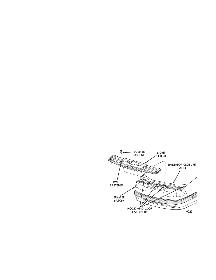
REMOVAL (FIG. 1)
(1) Raise hood to open position.
(2) Loosen twist fasteners holding headlamp covers
to fascia.
(3) Disengage hook and loop fasteners holding
sight shield to radiator closure panel.
(4) Remove push-in fasteners holding sight shield
to bumper fascia.
(5) Separate sight shield from vehicle.
INSTALLATION
Reverse the preceding operation.
HOOD AND HINGES
HOOD REMOVAL (FIG. 2)
(1) Raise hood to full up position.
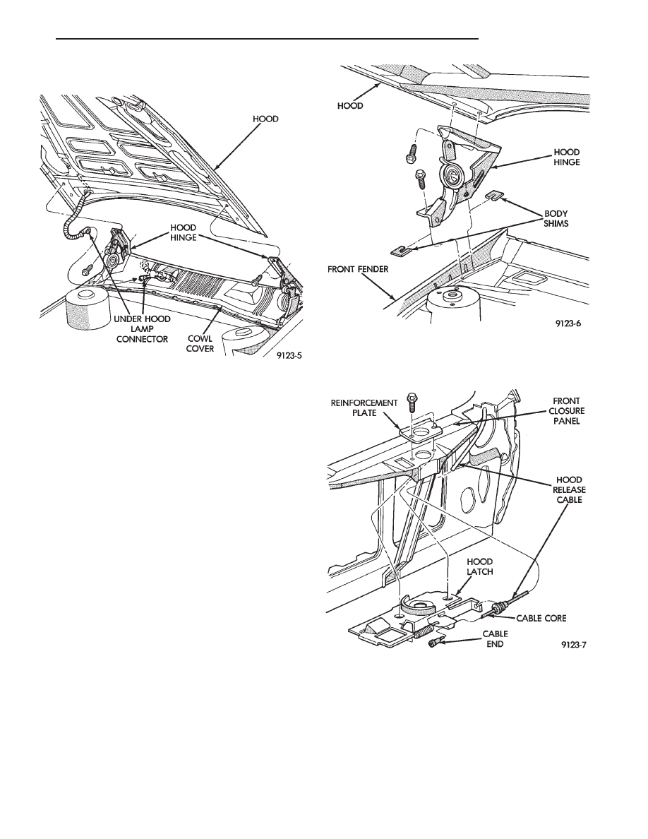
(2) Lift front edge of cowl cover on the right side of
the windshield washer bottle and disconnect the un-
der hood lamp wire connector.
(3) Mark all bolt and hinge attachment locations
with a grease pencil or other suitable device to pro-
vide reference marks for installation. When install-
ing hood, align all marks and secure bolts. The hood
should be aligned to 4 mm (0.160 in.) gap to the front
fenders and flush across the top surfaces along fend-
ers.
(4) Remove the top hood to hinge attaching bolts
and loosen the bottom bolts until they can be re-
moved by hand.
(5) With assistance of a helper at the opposite side
of the vehicle to support the hood, remove the bottom
hood to hinge attaching bolts. Separate the hood
from the vehicle.
Fig. 1 Closure Panel Sight Shield
23 - 52
AG-BODY
Ä
HOOD INSTALLATION
Reverse the preceding operation.
HOOD HINGE REMOVAL (FIG. 3)
(1) Support hood on the side that requires hinge
replacement.
(2) Mark all bolt and hinge attachment locations
with a grease pencil or other suitable device to pro-
vide reference marks for installation. When install-
ing hood hinge, align all marks and secure bolts. The
hood should be aligned to 4 mm (0.160 in.) gap to the
front fenders and flush across the top surfaces along
fenders. Shims can be added or removed under hood
hinge to achieve proper hood height.
(3) Remove hood to hinge attaching bolts.
(4) Remove hood hinge to front fender attaching
bolts and separate hinge from vehicle.
HOOD HINGE INSTALLATION
Reverse the preceding operation. If necessary, paint
new hinge before installation.
HOOD LATCH AND RELEASE CABLE
HOOD LATCH REMOVAL (FIG. 4)
(1) Raise hood to the full up position.
(2) Remove radiator closure panel sight shield.
(3) Remove hood latch attaching bolts holding
latch to radiator closure panel and separate from ve-
hicle.
(4) Pry release cable casing attachment from slot
receiver on latch, disengage cable end from latch arm
hook.
HOOD LATCH INSTALLATION
Reverse the preceding operation.
HOOD LATCH RELEASE CABLE REMOVAL
(FIG. 5)
(1) Raise hood to the full up position.
(2) Remove push-in fasteners holding sight shield
to radiator closure panel and separate cover from ve-
hicle.
(3) Disconnect hood release cable casing and cable
end from hood latch assembly. Refer to Hood Latch
Removal procedure in this section.
Fig. 2 Hood Assembly Remove or Install—Typical
Fig. 3 Hood Hinge Assembly—Typical
Fig. 4 Hood Latch Assembly—Typical
Ä
AG-BODY
23 - 53
Нет комментариевНе стесняйтесь поделиться с нами вашим ценным мнением.
Текст