Chrysler Le Baron, Dodge Dynasty, Plymouth Acclaim. Manual — part 323
COMPACT DISC PLAYER
WARNING: USE OF THE CONTROLS, ADJUST-
MENTS, OR SERVICE PROCEDURES NOT SPECI-
FIED HERE OR IN THE OWNER MANUAL MAY
RESULT IN HAZARDOUS RADIATION EXPOSURE.
REPAIR PROCEDURES SHOULD ONLY BE PER-
FORMED BY A TRAINED TECHNICIAN.
DIAGNOSIS TEST
Power to the compact disc player is supplied by the
radio through the CD interface cable. The compact
disc player will only work with the radio system
turned ON. When a compact disc is inserted with the
label side facing up, the disc is automatically loaded
and will begin to play.
The CD player may eject the disc with a display of
E under the following conditions:
• The surface of the disc is dirty or wet
• The disc was inserted with the label side facing
down
• The disc is defective
• The CD player may skip or mute while playing a
disc under severe vibration conditions example pot
holes, railroad tracks, etc.
• If the CD player becomes too hot at temperatures
above 60°C (140 °F) the CD player will shut down
with a display of HOT until it cools down. Refer to
the Audio Diagnostic Charts.
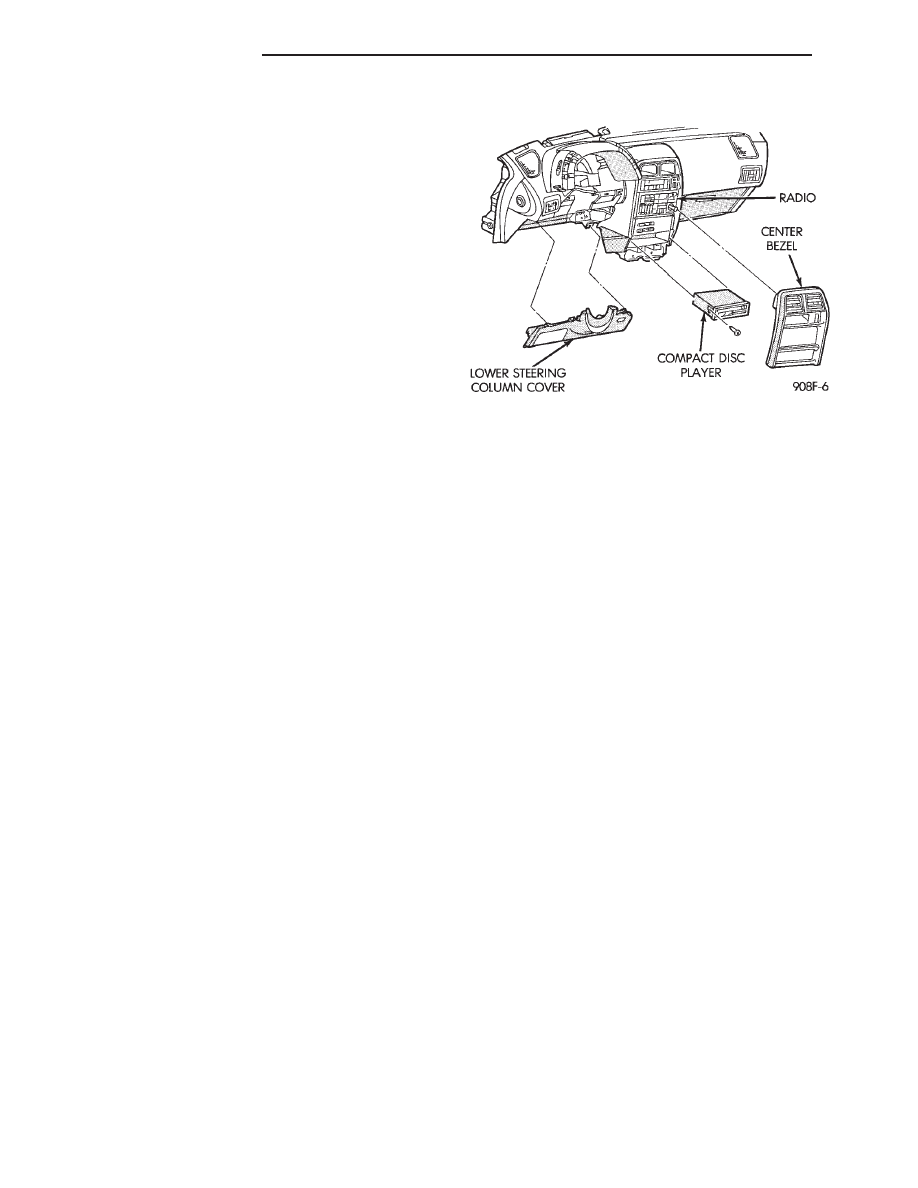
COMPACT DISC PLAYER REPLACEMENT
With intergral compact disc player refer to Radio
Removal.
AJ BODY
(1) Remove center instrument panel bezel by pull-
ing toward the rear of the car.
(2) Remove two screws attaching disc player to
console (Fig. 36).
(3) Pull disc player out of console and disconnect
interface cable.
(4) To install compact disc player, above the re-
moval procedures.
Fig. 36 Compact Disc Player
8F - 30
AUDIO SYSTEM
Ä

HORNS
CONTENTS
page
page
GENERAL INFORMATION . . . . . . . . . . . . . . . . . . 1
HORN SWITCH REPLACEMENT
. . . . . . . . . . . . 3
TESTING HORN SYSTEM
. . . . . . . . . . . . . . . . . 1
GENERAL INFORMATION
WARNING: ON VEHICLES EQUIPPED WITH AIR
BAG, SEE GROUP 8M, RESTRAINT SYSTEMS FOR
STEERING WHEEL OR COLUMN REMOVAL PROCE-
DURES.
The horn circuit consists of a horn switch, horn re-
lay, and horns. The horn circuit feed is from the fuse
box to the number 1 terminal on the horn relay.
When the horn switch is depressed, this completes
the circuit to ground. This activates the horn relay
and an set of contacts in the relay to close, which al-
lows current to flow to the horn(s). The horn ground
wire is attached to the headlamp ground screw (Fig.
1).
TESTING HORN SYSTEM
HORNS WILL NOT SOUND
If the horns do not sound, check for a blown horn
fuse in the fuse block. If the fuse is blown, replace it
with the same fuse type. If the horns fail to sound
and the new fuse blows when depressing the horn
switch, a short circuit in the horn or the horn wiring
between the fuse terminal and the horn is responsi-
ble.
If the fuse is good, disconnect wire connector at
horn. Using an test lamp, connect one lead to the
negative terminal and the other to the positive ter-
minal (Fig. 2). Depress the horn switch, the test
lamp should illuminate. If not connect the test lamp
wire to a good ground and depress the horn switch. If
test lamp lights inspect ground wire circuit and re-
pair as needed.
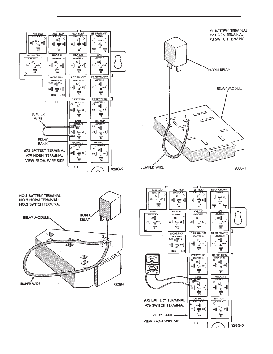
If the test lamp fails to illuminate, check for a de-
fective horn relay. Substituting a known good horn
relay in the circuit. If the test lamp illuminates
when depressing the horn switch, the original relay
is defective. If the test lamp fails to illuminate with
a known good relay, unplug that relay. Connect a
jumper wire from the battery terminal to the horn
terminal on the relay terminal board (Fig. 3, 4, or 5).
If the test lamp connected in place of the horns, fails
to illuminate an open circuit in the wiring between
the relay terminal and the horn switch is at fault re-
pair as necessary.
HORNS SOUND CONTINUOUSLY
CAUTION: Continuous sounding of horns may
cause relay to fail.
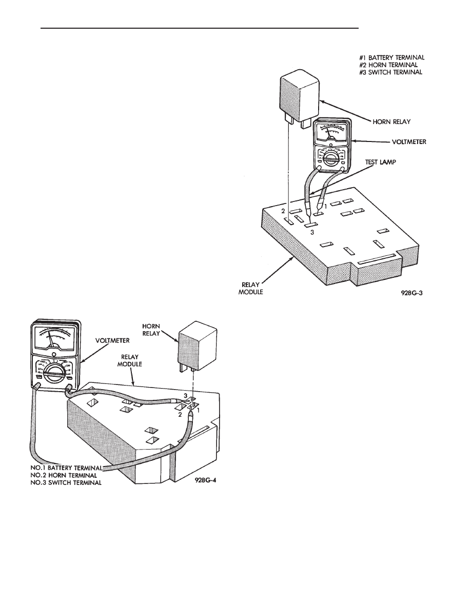
Should the horns sound continuously, unplug the
horn relay from the terminal board inside the pas-
senger compartment. Plug in a known good relay. If
the horns stop blowing, relay is defective and must
be replaced. Should the horns still sound, proceed as
follows: Connect one voltmeter lead to battery termi-
nal on relay board and the other lead to switch ter-
minal. Refer to Figs. 6, 7, or 8. Voltmeter will
Fig. 1 Conventional Horn System
Fig. 2 Horn and Connector
Ä
HORNS
8G - 1
register battery voltage when the wire to the horn
switch is shorted to ground or the horn switch is de-
fective.
Fig. 3 Testing for an Open Circuit—AG and AJ Bodies
Fig. 4 Testing for an Open Circuit—AP and AA Bodies
Fig. 5 Testing for an Open Circuit—AC and AY Bodies
Fig. 6 Testing for Short to Ground—AG and AJ Bodies
8G - 2
HORNS
Ä
Remove steering wheel horn pad and disconnect
wire from horn switch. Repeat the above test and if
the test lamp still illuminates, wire is shorted and
should be repaired. If test lamp does not illuminate,
horn switch is defective and must be replaced.
DIAGNOSIS TESTING
Horn does not sound, horn sounds intermittently,
or horn sounds continuously go to Horn Diagnosis
Chart (Fig. 9).
HORN SWITCH REPLACEMENT
WARNING: BEFORE BEGINNING ANY AIR BAG
SYSTEM REMOVAL OR INSTALLATION PROCE-
DURES, REMOVE AND ISOLATE THE NEGATIVE (-)
BATTERY CABLE (GROUND) FROM THE VEHICLE
BATTERY. THIS IS THE ONLY SURE WAY TO DIS-
ABLE THE AIR BAG SYSTEM. FAILURE TO DO
THIS COULD RESULT IN ACCIDENTAL AIR BAG
DEPLOYMENT AND POSSIBLE PERSONAL INJURY.
(1) Disconnect and isolate negative battery cable
in engine compartment.
(2) Remove four retaining nuts from back of steer-
ing wheel. Remove air bag module (Fig. 10 and 11).
(a) Disconnect wire from rear of air bag module.
(b) Place air bag module on a clean level surface
with pad facing upward.
(3) Remove horn switch assembly from steering
wheel.
(a) On luxury steering wheel (Fig. 10), pry out
two trim cover buttons on back of steering wheel to
access retaining screws for the horn switch. The
sport steering wheel (Fig. 11) the horn screws are
accessible after the Air Bag is removed.
(b) Remove two screws and disconnect horn wires
located in the lower portion of steering wheel. Feed
wires through the access ports and remove horn
switch.
(4) For installation reverse the above procedures.
Use caution not to pinch wires.
Fig. 8 Testing Horn for Continuous Sound— AP and
AA Bodies
Fig. 7 Testing for Short to Ground—AC and AY Bodies
Ä
HORNS
8G - 3
Нет комментариевНе стесняйтесь поделиться с нами вашим ценным мнением.
Текст