Chrysler Le Baron, Dodge Dynasty, Plymouth Acclaim. Manual — part 220
SERVICE PRECAUTIONS
WARNING: DUST AND DIRT ON BRAKE PARTS
GENERATED DURING THE NORMAL USE AND
WEAR OF MOTOR VEHICLE BRAKE SYSTEMS CAN
CONTAIN ASBESTOS FIBERS. BREATHING EXCES-
SIVE CONCENTRATIONS OF ASBESTOS FIBERS
CAN CAUSE SERIOUS BODILY HARM, SUCH AS
ASBESTOSIS
AND
CANCER.
EXTREME
CARE
SHOULD
BE
EXERCISED
WHILE
SERVICING
BRAKE ASSEMBLIES OR COMPONENTS.
DO NOT CLEAN BRAKE ASSEMBLIES OR COM-
PONENTS WITH COMPRESSED AIR OR BY DRY
BRUSHING; USE A VACUUM CLEANER SPECIFI-
CALLY RECOMMENDED FOR USE WITH ASBES-
TOS FIBERS. IF A SUITABLE VACUUM CLEANER IS
NOT AVAILABLE, CLEANING SHOULD BE DONE
WET USING A WATER DAMPENED CLOTH.
DO NOT CREATE DUST BY SANDING, GRINDING,
AND/OR SHAVING BRAKE LININGS OR PADS UN-
LESS SUCH OPERATION IS DONE WHILE USING
PROPERLY EXHAUST VENTILATED EQUIPMENT.
DISPOSE OF ALL DUST AND DIRT SUSPECTED
TO CONTAIN ANY ASBESTOS FIBERS IN SEALED
BAGS OR CONTAINERS TO MINIMIZE DUST EXPO-
SURE TO YOURSELF AND OTHERS.
FOLLOW ALL RECOMMENDED PRACTICES PRE-
SCRIBED BY THE OCCUPATIONAL SAFETY AND
HEALTH ADMINISTRATION AND THE ENVIRONMEN-
TAL PROTECTION AGENCY. FOR THE HANDLING,
PROCESSING, AND DISPOSITION OF DUST OR DIRT
WHICH MAY CONTAIN ASBESTOS FIBERS.
IT IS RECOMMENDED NOT TO BREATH ANY TYPE
OF BRAKE LINING MATERIAL DUST EVEN ASBES-
TOS FREE, DUE TO THE FIBROUS NATURE OF THE
MATERIALS BEING USED.
Grease or any other foreign material must be kept off
caliper assembly, surfaces of braking disc and external
surfaces of hub, during service procedures.
Handling of the braking disc and caliper. Should be
done in such a way as to avoid deformation of the disc
and scratching or nicking of the brake linings.
If inspection reveals that the square sectioned cali-
per piston seal is worn or damaged, it should be
replaced immediately.
During removal and installation of a wheel and tire
assembly, use care not to strike the caliper.
Before vehicle is moved after any brake service
work, be sure to obtain a firm brake pedal.
5 - 34
BRAKES
Ä
KELSEY HAYES DOUBLE PIN FAMILY CALIPER
BRAKE SHOE SERVICE PROCEDURES
BRAKE SHOE REMOVAL
(1) Raise vehicle on jackstands or centered on a
hoist. See Hoisting Information in the Lubrication
and Maintenance section of this manual.
(2) Remove front wheel and tire assemblies.
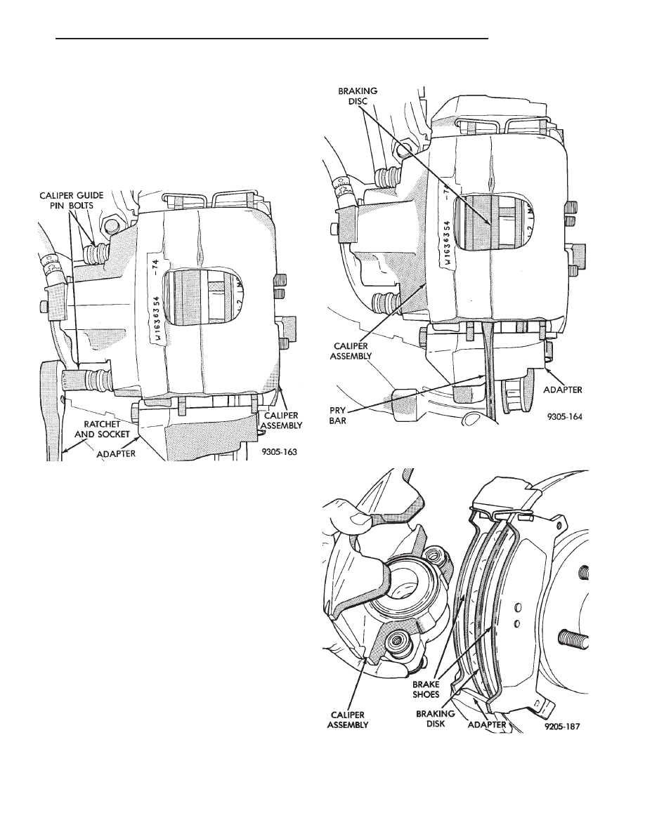
(3) Remove caliper guide pin bolts (Fig. 1).
(4) After removing caliper guide pin bolts. Lift cal-
iper away from braking disc using a pry bar or
screwdriver (Fig. 2).
(5) Remove caliper assembly from braking disc and
adapter by sliding the assembly out and away from
the braking disc and adapter (Fig. 3).
(6) Support caliper firmly to prevent weight of cal-
iper from damaging the flexible brake hose (Fig. 4).
(7) Remove the outboard brake shoe assembly from
the caliper adapter (Fig. 5).
(8) Remove the braking disk (rotor) from the hub
by pulling it straight off the wheel mounting studs
(Fig. 6).
Fig. 1 Removing or Installing Caliper Guide Pin
Bolts
Fig. 2 Loosening Family Caliper Assembly From
Adapter And Rotor
Fig. 3 Removing or Installing Caliper Assembly
Ä
BRAKES
5 - 35
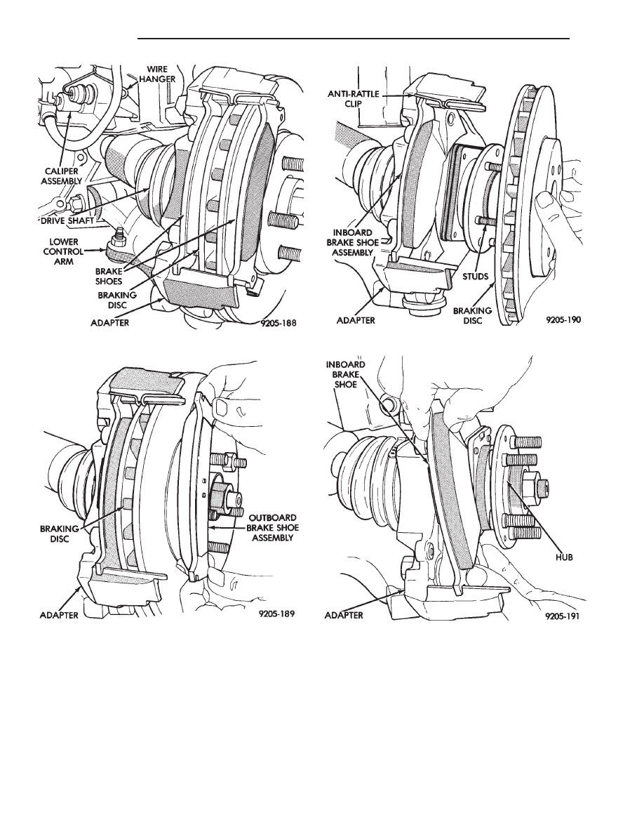
(9) Remove the inboard brake shoe assembly by
sliding it out along the bottom adapter abutment un-
til brake shoe assembly loosens from anti-rattle clip
(Fig. 7).
(10) Remove the anti-rattle clip from the top
adapter abutment (Fig. 8).
BRAKE SHOE INSTALLATION
(1) Thoroughly clean and lubricate both adapter
abutments with a liberal amount of Mopar
t Multi-
purpose Lubricant, or equivalent.
(2) Install the anti-rattle clip on the upper abut-
ment of the caliper mounting adapter (Fig. 8).
(3) Install the new inboard brake shoe assembly on
the adapter by sliding it along the adapter abut-
ments. Be careful not to get any grease from the
adapter abutment on the surface of the brake lining
Fig. 4 Storing Caliper
Fig. 5 Removing and Installing Outboard Shoe
Assembly
Fig. 6 Removing or Installing Braking Disc
Fig. 7 Removing or Installing Inboard Shoe
Assembly
5 - 36
BRAKES
Ä

material, (Fig. 7). Be sure inboard brake shoe assem-
bly is correctly positioned against anti-rattle clip
(Fig. 6).
(4) Reinstall the Braking Disk on the hub, by in-
stalling it over the wheel studs until it is seated
against the face of the hub (Fig. 6).
(5) Slide the new outboard brake shoe assembly on
the adapter abutment, (Fig. 5).
(6) Carefully lower caliper over the braking disk and
brake shoe assemblies (Fig. 3). Make sure that the
caliper guide pin bolt, bushings and sleeves are clear of
the adapter.
(7) Install the caliper guide pin bolts and tighten to
34 to 37 N
Im (25 to 35 ft. lbs.). Extreme caution
should be taken not to cross the threads of the
caliper guide pin bolts.
(8) Install the wheel and tire assembly. Tighten the
wheel mounting stud nuts in proper sequence (Fig. 9)
until all nuts are torqued to half specification. This is
important. Then repeat the tightening sequence to the
full specified torque of 129 N
Im (95 ft. lbs.).
(9) Remove jackstands or lower hoist. Before mov-
ing vehicle, pump the brake pedal several times
to insure the vehicle has a firm brake pedal to
adequately stop vehicle..
(10) Road test the vehicle and make several stops to
wear off any foreign material on the brake linings and
to seat the brake shoe linings.
Fig. 8 Remove Or Replace Anti-Rattle Clip
Fig. 9 Tightening Wheel Nuts
Ä
BRAKES
5 - 37
Нет комментариевНе стесняйтесь поделиться с нами вашим ценным мнением.
Текст