Infiniti FX35 / FX45. Manual — part 789
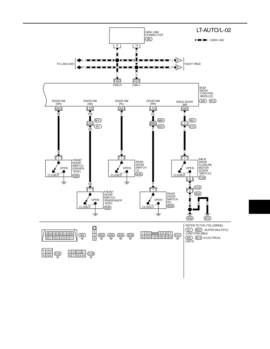
AUTO LIGHT SYSTEM
LT-51
< SERVICE INFORMATION >
C
D
E
F
G
H
I
J
L
M
A
B
LT
N
O
P
TKWM4298E
LT-52
< SERVICE INFORMATION >
AUTO LIGHT SYSTEM
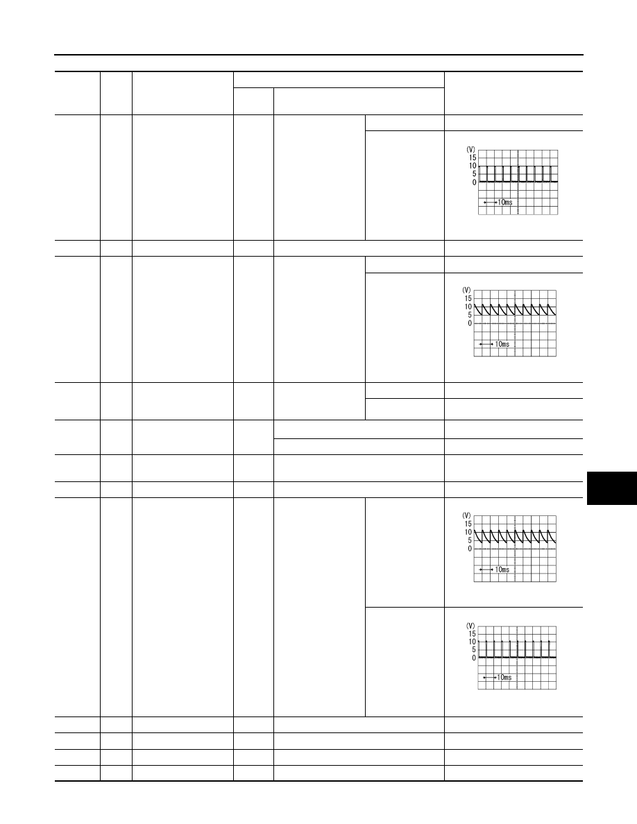
Terminal and Reference Value for BCM
INFOID:0000000001328313
CAUTION:
• Check combination switch system terminal waveform under the loaded condition with lighting
switch, turn signal switch and wiper switch OFF not to be fluctuated by overloaded.
• Turn wiper intermittent dial position to 4 except when checking waveform or voltage of wiper inter-
mittent dial position. Wiper intermittent dial position can be confirmed on CONSULT-III. Refer to
103, "CONSULT-III Functions (BCM)"
TKWM4299E
AUTO LIGHT SYSTEM
LT-53
< SERVICE INFORMATION >
C
D
E
F
G
H
I
J
L
M
A
B
LT
N
O
P
Terminal
No.
Wire
color
Signal name
Measuring condition
Reference value
Ignition
switch
Operation or condition
4
Pu/W
Combination switch in-
put 3
ON
Lighting, turn, wiper
switch
(Wiper intermittent
dial position 4)
OFF
Approx. 0 V
Lighting switch
AUTO
Approx. 1.0 V
11
LG
Ignition switch (ACC)
ACC
—
Battery voltage
12
P/B
Front door switch
(Passenger side) signal
OFF
Front door switch
(Passenger side)
ON (open)
Approx. 0 V
OFF (closed)
Approx. 7.5 - 8.0 V
13
P/L
Rear door switch RH
signal
OFF
Rear door switch RH
(Personal lamp RH
ON or OFF position)
ON (open)
Approx. 0 V
OFF (closed)
Battery voltage
14
P
Optical sensor signal
ON
When optical sensor is illuminated
3.1 V or more
Note
When optical sensor is not illuminated
0.6 V or less
17
Y/G
Optical sensor power
supply
ON
—
Approx. 5 V
18
B
Sensor ground
ON
—
Approx. 0 V
33
G
Combination switch
output 4
ON
Lighting, turn, wiper
switch
(Wiper intermittent
dial position 4)
OFF
Approx. 7.2 V
Lighting switch
AUTO
Approx. 1.2 V
38
W/L
Ignition switch (ON)
ON
—
Battery voltage
39
L
CAN
−
H
—
—
—
40
P
CAN
−
L
—
—
—
42
L/R
Battery power supply
OFF
—
Battery voltage
PKIB4959J
SKIB3419J
PKIB4960J
PKIB4958J
LT-54
< SERVICE INFORMATION >
AUTO LIGHT SYSTEM
NOTE:
Optical sensor must be securely subjected to work lamp light. If optical sensor is insufficiently illuminated, the measured value may not
satisfy standard.
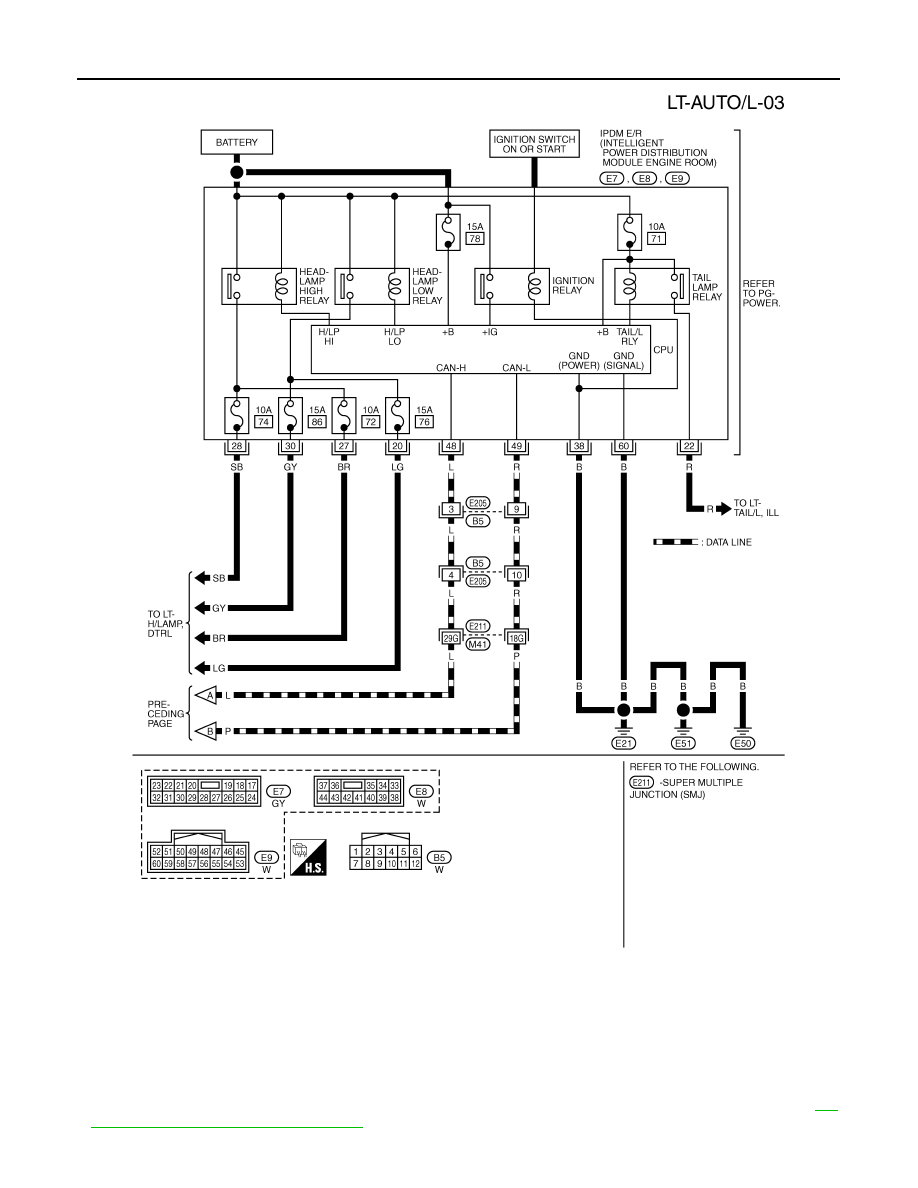
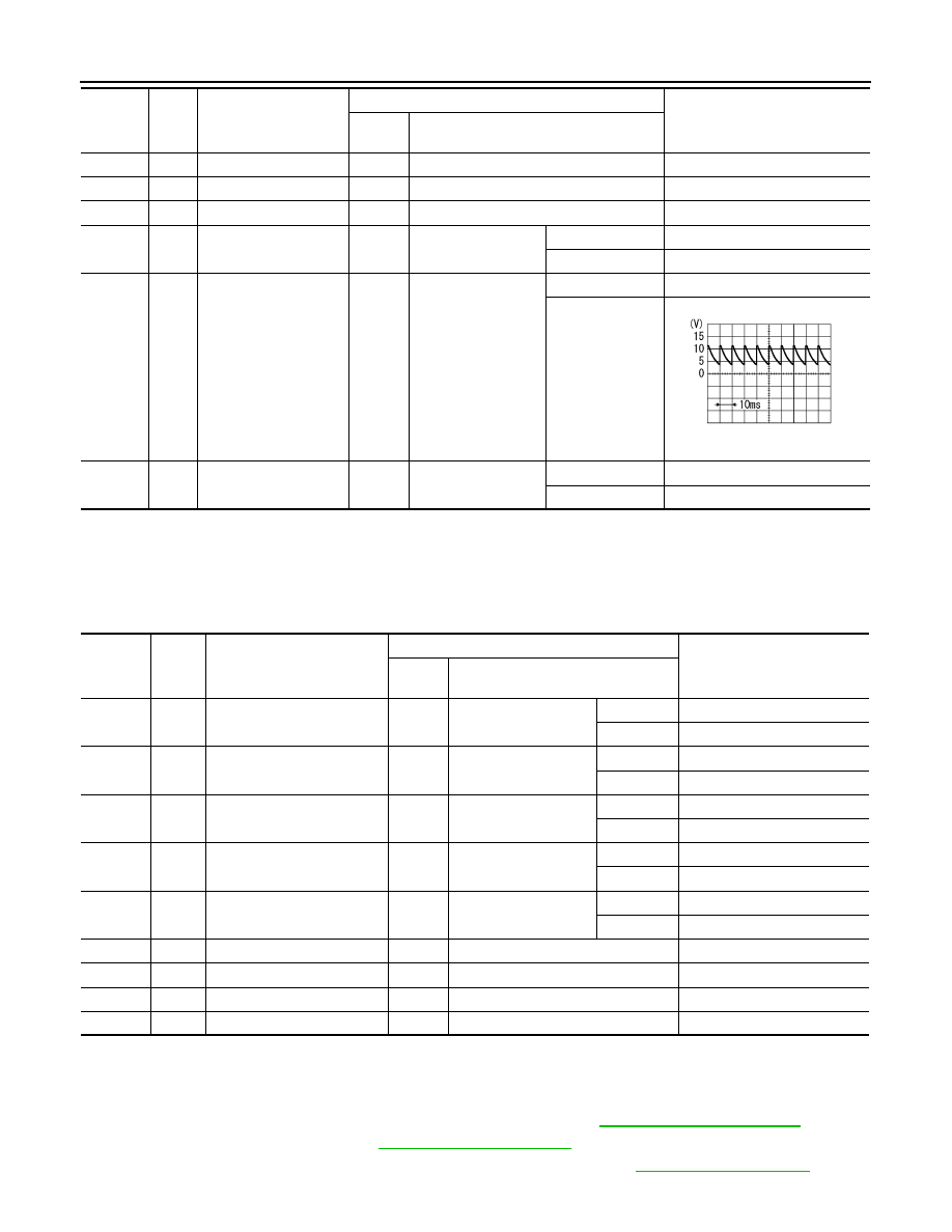
Terminal and Reference Value for IPDM E/R
INFOID:0000000001328314
How to Proceed with Trouble Diagnosis
INFOID:0000000001328315
1.
Confirm the symptom or customer complaint.
2.
Understand operation description and function description. Refer to
.
3.
Perform Preliminary Check. Refer to
4.
Check symptom and repair or replace the cause of malfunction. Refer to
.
49
B
Ground
ON
—
Approx. 0 V
52
B
Ground
ON
—
Approx. 0 V
55
G
Battery power supply
OFF
—
Battery voltage
58
L
Back door switch signal
OFF
Back door closure
motor (door switch)
ON (open)
Approx. 0 V
OFF (closed)
Battery voltage
62
W
Front door switch
(Driver side) signal
OFF
Front door switch
(Driver side)
ON (open)
Approx. 0 V
OFF (closed)
Approx. 7.0 - 7.5 V
63
P
Rear door switch LH
signal
OFF
Rear door switch LH
ON (open)
Approx. 0 V
OFF (closed)
Battery voltage
Terminal
No.
Wire
color
Signal name
Measuring condition
Reference value
Ignition
switch
Operation or condition
PKIB4960J
Terminal
No.
Wire
color
Signal name
Measuring condition
Reference value
Ignition
switch
Operation or condition
20
LG
Headlamp low (RH)
ON
Lighting switch 2ND
position
OFF
Approx. 0 V
ON
Battery voltage
22
R
Parking, license plate, side
marker and tail lamps
ON
Lighting switch 1ST po-
sition
OFF
Approx. 0 V
ON
Battery voltage
27
BR
Headlamp high (RH)
ON
Lighting switch HIGH
or PASS position
OFF
Approx. 0 V
ON
Battery voltage
28
SB
Headlamp high (LH)
ON
Lighting switch HIGH
or PASS position
OFF
Approx. 0 V
ON
Battery voltage
30
GY
Headlamp low (LH)
ON
Lighting switch 2ND
position
OFF
Approx. 0 V
ON
Battery voltage
38
B
Ground
ON
—
Approx. 0 V
48
L
CAN
−
H
—
—
—
49
R
CAN
−
L
—
—
—
60
B
Ground
ON
—
Approx. 0 V
Нет комментариевНе стесняйтесь поделиться с нами вашим ценным мнением.
Текст