Infiniti FX35 / FX45. Manual — part 788
AUTO LIGHT SYSTEM
LT-47
< SERVICE INFORMATION >
C
D
E
F
G
H
I
J
L
M
A
B
LT
N
O
P
AUTO LIGHT SYSTEM
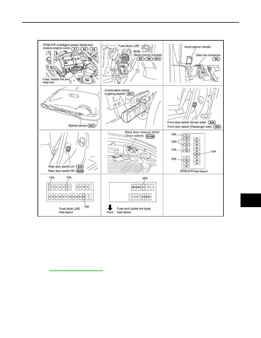
Component Parts and Harness Connector Location
INFOID:0000000001328306
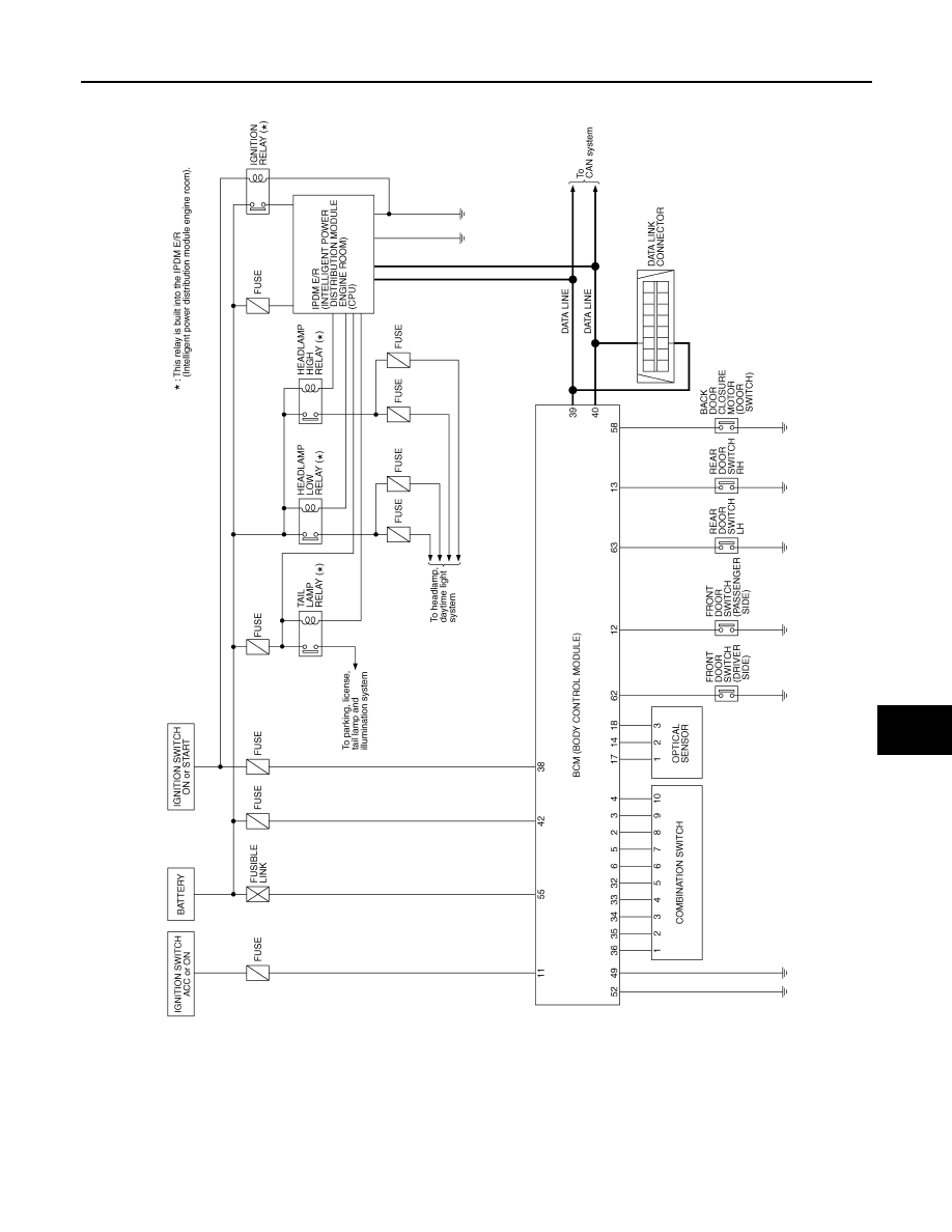
System Description
INFOID:0000000001328307
Automatically turns ON/OFF parking lamps and the headlamps in accordance with ambient light.
Timing for when the lamps turn ON/OFF can be selected using four modes.
OUTLINE
The auto light control system has an optical sensor inside it that detects outside brightness.
When the lighting switch is in AUTO position, it automatically turns ON/OFF the parking lamps and the head-
lamps in accordance with the ambient light. Sensitivity can be adjusted in four steps. For the details of the set-
ting, Refer to
Optical sensor control mode can be changed by the function setting of CONSULT-III or display.
Optical sensor, power is supplied
• from BCM (body control module) terminal 17
• to optical sensor terminal 1.
Optical sensor, ground is supplied
• to optical sensor terminal 3
• through BCM terminal 18.
When ignition switch is turn to ON position, and
When outside brightness is darker than prescribed level, input is supplied
• from optical sensor terminal 2
• to BCM terminal 14
PKIB3474E

LT-48
< SERVICE INFORMATION >
AUTO LIGHT SYSTEM
The headlamps will then illuminate. For a description of headlamp operation, Refer to
.
COMBINATION SWITCH READING FUNCTION
DELAY TIMER FUNCTION
Delay timer function carries out a function that BCM activates the timer and controls lights out of headlamps by
door switch signal and lightning switch signal when turning the Ignition switch OFF while it is ON and head-
lamps are ON by the auto light function.
Timer types are a 5 minute timer and a 45 second timer
• When opening any door (door switch is ON), the 5 minute timer starts and then headlamps go out 5 minutes
later
• When all the doors are closed (from door switch ON to OFF), the 45 second timer starts and then headlamps
go out 45 seconds later. If any door is opened (door switch ON) while the 45 second timer is in operation, the
5 minute timer starts again
• The timer stops when turning on the ignition switch or turning off the auto light switch under the above condi-
tions.
Delay timer control mode can be changed by the function setting of CONSULT-III or display.
CAN Communication System Description
INFOID:0000000001328308
CAN (Controller Area Network) is a serial communication line for real time application. It is an on-vehicle mul-
tiplex communication line with high data communication speed and excellent error detection ability. Many elec-
tronic control units are equipped onto a vehicle, and each control unit shares information and links with other
control units during operation (not independent). In CAN communication, control units are connected with 2
communication lines (CAN H line, CAN L line) allowing a high rate of information transmission with less wiring.
Each control unit transmits/receives data but selectively reads required data only.
CAN Communication Unit
INFOID:0000000001328309
LAN-43, "CAN System Specification Chart"
Major Component and Functions
INFOID:0000000001328310
Components
Functions
BCM
• Turns on/off circuits of tail light and headlamp according to signals from light sensor, lighting switch (AUTO),
driver door switch, passenger door switch, rear door switch, and ignition switch (ON, OFF).
Optical sensor
• Converts outside brightness (lux) to voltage, and sends it to BCM. (Detects brightness of 800 to 2,500 lux)
AUTO LIGHT SYSTEM
LT-49
< SERVICE INFORMATION >
C
D
E
F
G
H
I
J
L
M
A
B
LT
N
O
P
Schematic
INFOID:0000000001328311
TKWM0611E
LT-50
< SERVICE INFORMATION >
AUTO LIGHT SYSTEM
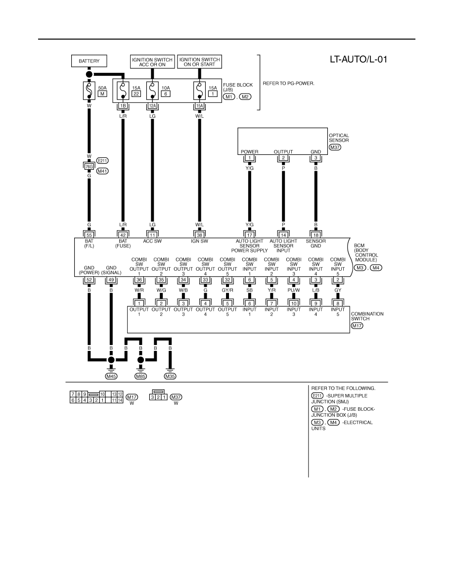
Wiring Diagram - AUTO/L -
INFOID:0000000001328312
TKWM4297E
Нет комментариевНе стесняйтесь поделиться с нами вашим ценным мнением.
Текст