Infiniti FX35 / FX45. Manual — part 787
DAYTIME LIGHT SYSTEM
LT-43
< SERVICE INFORMATION >
C
D
E
F
G
H
I
J
L
M
A
B
LT
N
O
P
1.
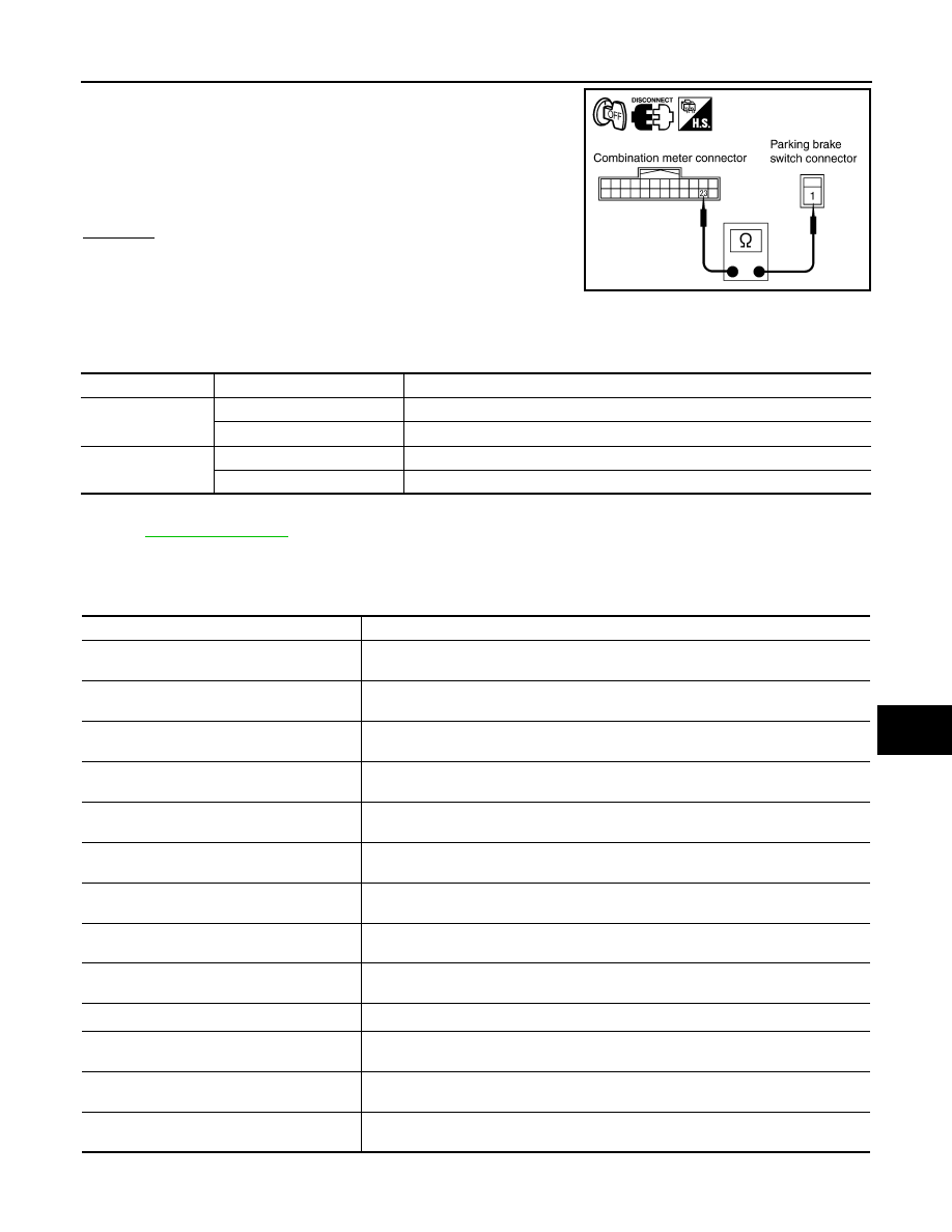
Turn ignition switch OFF.
2.
Disconnect combination meter connector.
3.
Check continuity between combination meter harness connector
M20 terminal 23 and parking brake switch harness connector
E207 terminal 1.
OK or NG
OK
>> Replace combination meter.
NG
>> Repair harness or connector.
CONSULT-III Functions (BCM)
INFOID:0000000001328300
CONSULT-III can display each diagnostic item using the diagnostic test mode shown following.
CONSULT-III BASIC OPERATION
.
DATA MONITOR
Display Item List
1 – 23
: Continuity should exist.
SKIA5877E
BCM diagnosis part
Diagnosis mode
Description
HEADLAMP
DATA MONITOR
Displays BCM input data in real time.
ACTIVE TEST
Operation of electrical loads can be checked by sending drive signal to them.
BCM
SELF-DIAG RESULTS
BCM performs self-diagnosis of CAN communication.
CAN DIAG SUPPORT MNTR
The result of transmit/receive diagnosis of CAN communication can be read.
Monitor item
Contents
IGN ON SW
“ON/OFF”
Displays “IGN position (ON)/OFF, ACC position (OFF)” judged from ignition switch sig-
nal.
ACC ON SW
“ON/OFF”
Displays “ACC (ON)/OFF, Ignition OFF (OFF)” status judged from ignition switch sig-
nal.
HI BEAM SW
“ON/OFF”
Displays status (high beam switch: ON/Others: OFF) of high beam switch judged from
lighting switch signal.
HEAD LAMP SW 1
“ON/OFF”
Displays status (headlamp switch 1: ON/Others: OFF) of headlamp switch 1 judged
from lighting switch signal.
HEAD LAMP SW 2
“ON/OFF”
Displays status (headlamp switch 2: ON/Others: OFF) of headlamp switch 2 judged
from lighting switch signal.
LIGHT SW 1 ST
“ON/OFF”
Displays status (lighting switch 1ST or 2ND position: ON/Others: OFF) of lighting
switch judged from lighting switch signal.
AUTO LIGHT SW
NOTE 1
“ON/OFF”
Displays status of lighting switch as judged from lighting switch signal. (AUTO position:
ON/Other than AUTO position: OFF)
PASSING SW
“ON/OFF”
Displays status (flash-to-pass switch: ON/Others: OFF) of flash-to-pass switch judged
from lighting switch signal.
FR FOG SW
“ON/OFF”
Displays status (front fog lamp switch: ON/Others: OFF) of front fog lamp switch
judged from lighting switch signal.
RR FOG SW
NOTE 3
“OFF”
—
DOOR SW - DR
“ON/OFF”
Displays status of driver door as judged from driver door switch signal. (Door is open:
ON/Door is closed: OFF)
DOOR SW - AS
“ON/OFF”
Displays status of passenger door as judged from passenger door switch signal. (Door
is open: ON/Door is closed: OFF)
DOOR SW - RR
“ON/OFF”
Displays status of rear door as judged from rear door switch (RH) signal. (Door is open:
ON/Door is closed: OFF)
LT-44
< SERVICE INFORMATION >
DAYTIME LIGHT SYSTEM
NOTE:
1.
Vehicles without auto light system display this item, but cannot be monitored.
2.
Vehicles without daytime light system display this item, but cannot be monitored.
3.
This item is displayed, but cannot be monitored.
ACTIVE TEST
Display Item List
NOTE:
1.
Vehicles without daytime light lamp system display this item, but cannot be tested.
2.
This item is displayed, but cannot be tested.
Daytime Light Control Does Not Operate Properly
INFOID:0000000001328301
1.
CHECK DAYTIME LIGHT RELAY POWER SUPPLY CIRCUIT
1.
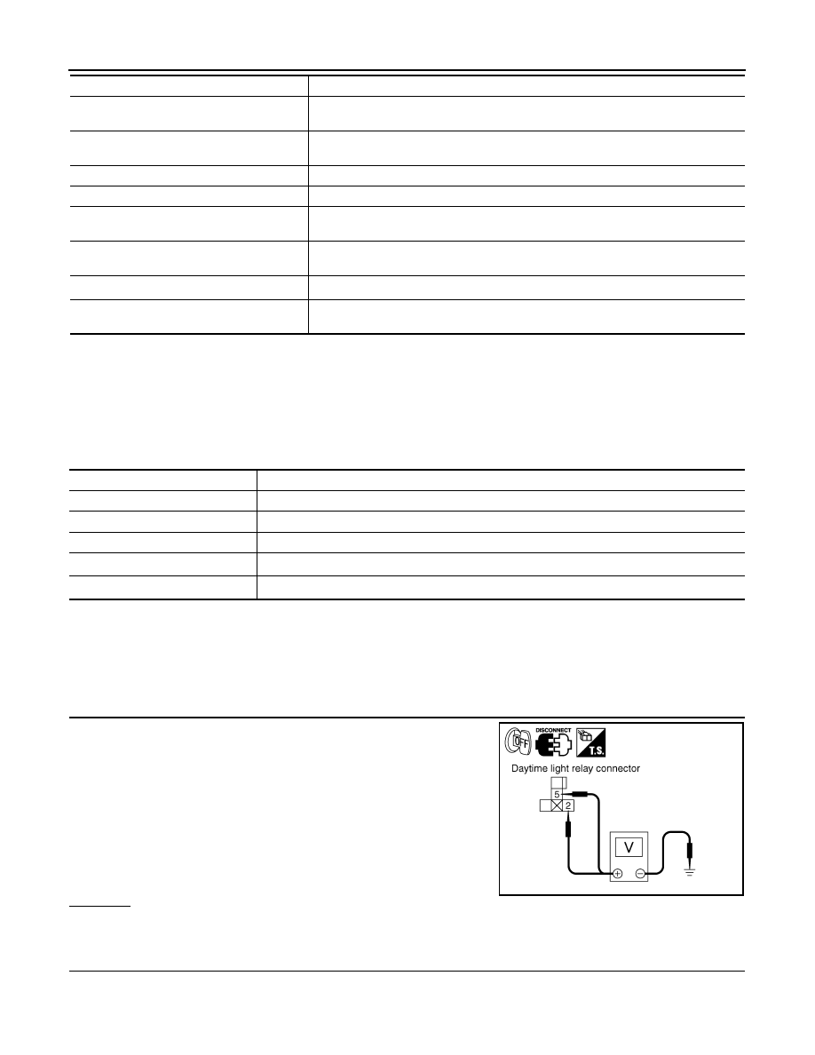
Turn ignition switch OFF.
2.
Remove daytime light relay.
3.
Check voltage between daytime light relay harness connector
E15 terminal 2 and ground.
4.
Check voltage between daytime light relay harness connector
E15 terminal 5 and ground.
OK or NG
OK
>> GO TO 2.
NG
>> Repair harness or connector.
2.
CHECK DAYTIME LIGHT RELAY
DOOR SW - RL
“ON/OFF”
Displays status of rear door as judged from rear door switch (LH) signal. (Door is open:
ON/Door is closed: OFF)
BACK DOOR SW
“ON/OFF”
Displays status of back door as judged from back door switch signal. (Door is open:
ON/Door is closed: OFF)
TURN SIGNAL R
“ON/OFF”
Displays status (Turn right: ON/Others: OFF) as judged from lighting switch signal.
TURN SIGNAL L
“ON/OFF”
Displays status (Turn left: ON/Others: OFF) as judged from lighting switch signal.
ENGINE RUN
NOTE 2
“ON/OFF”
Displays status (Engine running: ON/Others: OFF) as judged from engine status sig-
nal.
PKB SW
NOTE 2
“ON/OFF”
Displays status (Parking brake switch: ON/Others: OFF) as judged from parking brake
switch signal.
CARGO LAMP SW
NOTE 3
“OFF”
—
OPTICAL SENSOR
NOTE 1
“0 – 5 V”
Displays “outside brightness (close to 5 V when light/close to 0 V when dark)” judged
from optical sensor signal.
Monitor item
Contents
Test item
Description
TAIL LAMP
Allows tail lamp relay to operate by switching ON-OFF
HEAD LAMP
Allows headlamp relay to operate by switching ON-OFF.
FR FOG LAMP
Allows front fog lamp relay to operate by switching ON-OFF
DTRL
NOTE 1
Allows daytime light lamp operate by switching ON-OFF
CORNERING LAMP
NOTE 2
—
2 – Ground
: Battery voltage.
5 – Ground
: Battery voltage.
PKIA5274E
DAYTIME LIGHT SYSTEM
LT-45
< SERVICE INFORMATION >
C
D
E
F
G
H
I
J
L
M
A
B
LT
N
O
P
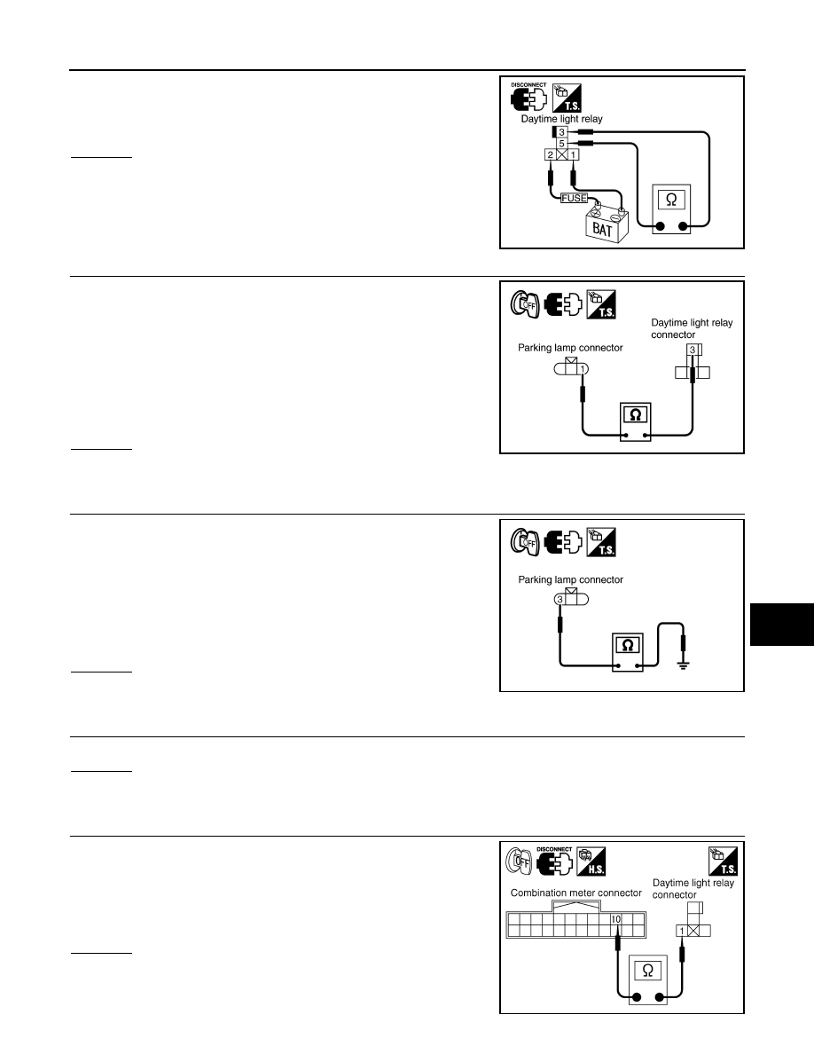
Apply battery voltage to between daytime light relay terminal 1, 2
and check continuity between terminal 3 and 5.
OK or NG
OK
>> GO TO 3.
NG
>> Replace daytime light relay.
3.
CHECK DAYTIME LIGHT RELAY CIRCUIT
1.
Disconnect parking lamp RH and LH connectors.
2.
Check continuity between daytime light relay connector E15 ter-
minal 3 and parking lamp RH harness connector E23 terminal 1.
3.
Check continuity between daytime light relay connector E15 ter-
minal 3 and parking lamp LH harness connector E43 terminal 1.
OK or NG
OK
>> GO TO 4.
NG
>> Repair harness or connector.
4.
CHECK GROUND
1.
Check continuity between parking lamp RH harness connector
E23 terminal 3 and ground.
2.
Check continuity between parking lamp LH harness connector
E43 terminal 3 and ground.
OK or NG
OK
>> GO TO 5.
NG
>> Repair harness or connector.
5.
CHECK BULB
Inspect bulbs of lamp which do not illuminate.
OK or NG
OK
>> GO TO 6.
NG
>> Replace bulb.
6.
CHECK DAYTIME RELAY CIRCUIT
1.
Disconnect combination meter connector.
2.
Check continuity between daytime lamp relay harness connec-
tor E15 terminal 1 and combination meter harness connector
M20 terminal 10.
OK or NG
OK
>> GO TO 7.
NG
>> Repair harness or connector.
3 – 5
: Continuity should exist.
PKIA5214E
3 – 1
: Continuity should exist.
3 – 1
: Continuity should exist.
PKIC9687E
3 – Ground
: Continuity should exist.
3 – Ground
: Continuity should exist.
PKIC9688E
1 – 10
: Continuity should exist.
PKIA5216E

LT-46
< SERVICE INFORMATION >
DAYTIME LIGHT SYSTEM
7.
CHECK INPUT SIGNAL
CONSULT-III DATA MONITOR
1.
Select “HEAD LAMP” of BCM data monitor item.
2.
With the engine running or stopped, check the monitor status.
3.
Select “HEAD LAMP” of BCM data monitor item.
4.
With operating the parking brake switch, check the monitor status.
OK or NG
OK
>> Replace BCM. Refer to
BCS-13, "Removal and Installation of BCM"
.
NG
>> GO TO 8.
8.
CHECKING CAN COMMUNICATIONS
1.
Select “self-diagnosis” of BCM”.
2.
Check display content in self-diagnosis results.
Displayed self-diagnosis results
NO DTC>> Replace BCM. Refer to
BCS-13, "Removal and Installation of BCM"
CAN COMM CIRCUIT>> Check BCM CAN communication system. Refer to
.
Aiming Adjustment
INFOID:0000000001328302
.
Bulb Replacement
INFOID:0000000001328303
Removal and Installation
INFOID:0000000001328304
LT-30, "Removal and Installation"
.
Disassembly and Assembly
INFOID:0000000001328305
LT-30, "Disassembly and Assembly"
.
Engine running
: ENGINE RUN ON
Engine stop
: ENGINE RUN OFF
Parking brake ON
: PKB SW ON
Parking brake OFF
: PKB SW OFF
Нет комментариевНе стесняйтесь поделиться с нами вашим ценным мнением.
Текст