Infiniti FX35 / FX45. Manual — part 180
BCS-1
ELECTRICAL
C
D
E
F
G
H
I
J
L
M
SECTION
BCS
A
B
BCS
N
O
P
CONTENTS
BODY CONTROL SYSTEM
SERVICE INFORMATION . . . . . . .
DTC INDEX . . . . . . . . . . . . . . ..
U1000 . . . . . . . . . . . . . . . . . ....
PRECAUTIONS . . . . . . . . . . . . ...
BCM (BODY CONTROL MODULE) . . . . ..
System Description . . . . . . . . . . . . ...
CAN Communication Unit . . . . . . . . . . .
Schematic . . . . . . . . . . . . . . . .
CONSULT-III Function (BCM) . . . . . . . . .
U1000 CAN Communication Circuit . . . . . .

BCS-2
< SERVICE INFORMATION >
DTC INDEX
SERVICE INFORMATION
DTC INDEX
U1000
INFOID:0000000001351357
DTC
Items (CONSULT screen terms)
Reference
U1000
CAN COMM CIRCUIT
PRECAUTIONS
BCS-3
< SERVICE INFORMATION >
C
D
E
F
G
H
I
J
L
M
A
B
BCS
N
O
P
PRECAUTIONS
Precaution for Supplemental Restraint System (SRS) "AIR BAG" and "SEAT BELT
PRE-TENSIONER"
INFOID:0000000001612912
The Supplemental Restraint System such as “AIR BAG” and “SEAT BELT PRE-TENSIONER”, used along
with a front seat belt, helps to reduce the risk or severity of injury to the driver and front passenger for certain
types of collision. This system includes seat belt switch inputs and dual stage front air bag modules. The SRS
system uses the seat belt switches to determine the front air bag deployment, and may only deploy one front
air bag, depending on the severity of a collision and whether the front occupants are belted or unbelted.
Information necessary to service the system safely is included in the “SUPPLEMENTAL RESTRAINT SYS-
TEM” and “SEAT BELTS” of this Service Manual.
WARNING:
• To avoid rendering the SRS inoperative, which could increase the risk of personal injury or death in
the event of a collision which would result in air bag inflation, all maintenance must be performed by
an authorized NISSAN/INFINITI dealer.
• Improper maintenance, including incorrect removal and installation of the SRS, can lead to personal
injury caused by unintentional activation of the system. For removal of Spiral Cable and Air Bag
Module, see the “SUPPLEMENTAL RESTRAINT SYSTEM”.
• Do not use electrical test equipment on any circuit related to the SRS unless instructed to in this
Service Manual. SRS wiring harnesses can be identified by yellow and/or orange harnesses or har-
ness connectors.
BCS-4
< SERVICE INFORMATION >
BCM (BODY CONTROL MODULE)
BCM (BODY CONTROL MODULE)
System Description
INFOID:0000000001328608
BCM (Body Control Module) controls the operation of various electrical units installed on the vehicle.
BCM FUNCTION
BCM has combination switch reading function for reading the operation of combination switches (light, wiper,
washer and turn signal) in addition to a function for controlling the operation of various electrical components.
Also it has an interface function allowing it to receive signals from the unified meter and A/C amp., and send
signals to ECM using CAN communication.
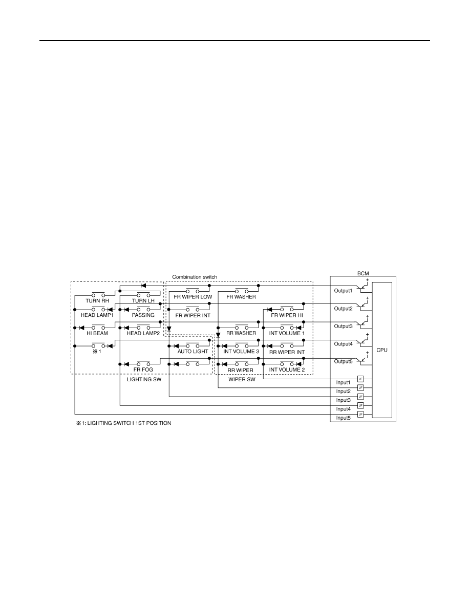
COMBINATION SWITCH READING FUNCTION
Description
• BCM reads combination switch (lighting switch, wiper switch) status, and controls various electrical compo-
nent according to the result.
• BCM reads information of a maximum of 20 switches by combining five output terminals (OUTPUT 1-5) and
five input terminals (INPUT 1-5).
Operation Description
• BCM activates transistors of output terminals (OUTPUT 1-5) periodically, and allows current to flow in turn.
• If any (1 or more) switches are turned ON, circuit of output terminals (OUTPUT 1-5) and input terminals
(INPUT 1-5) becomes active.
• At this time, transistors of output terminals (OUTPUT 1-5) are activated to allow current to flow. When volt-
age of input terminals (INPUT 1-5) corresponding to that switch changes, interface in BCM detects voltage
change, and BCM determines that switch is ON.
Operation Table Of BCM and Combination Switches
PKID0853E
Нет комментариевНе стесняйтесь поделиться с нами вашим ценным мнением.
Текст