Infiniti FX35 / FX45. Manual — part 158
AV-86
< SERVICE INFORMATION >
INTEGRATED DISPLAY SYSTEM
Example of Symptom Possible No Malfunction
INFOID:0000000001328735
For system operation information, refer to Owner's Manual.
DISPLAY
Removal and Installation of Display
INFOID:0000000001328736
AV-42, "Disassembly and Assembly of Audio Unit"
.
Removal and Installation of Display Control Unit
INFOID:0000000001328737
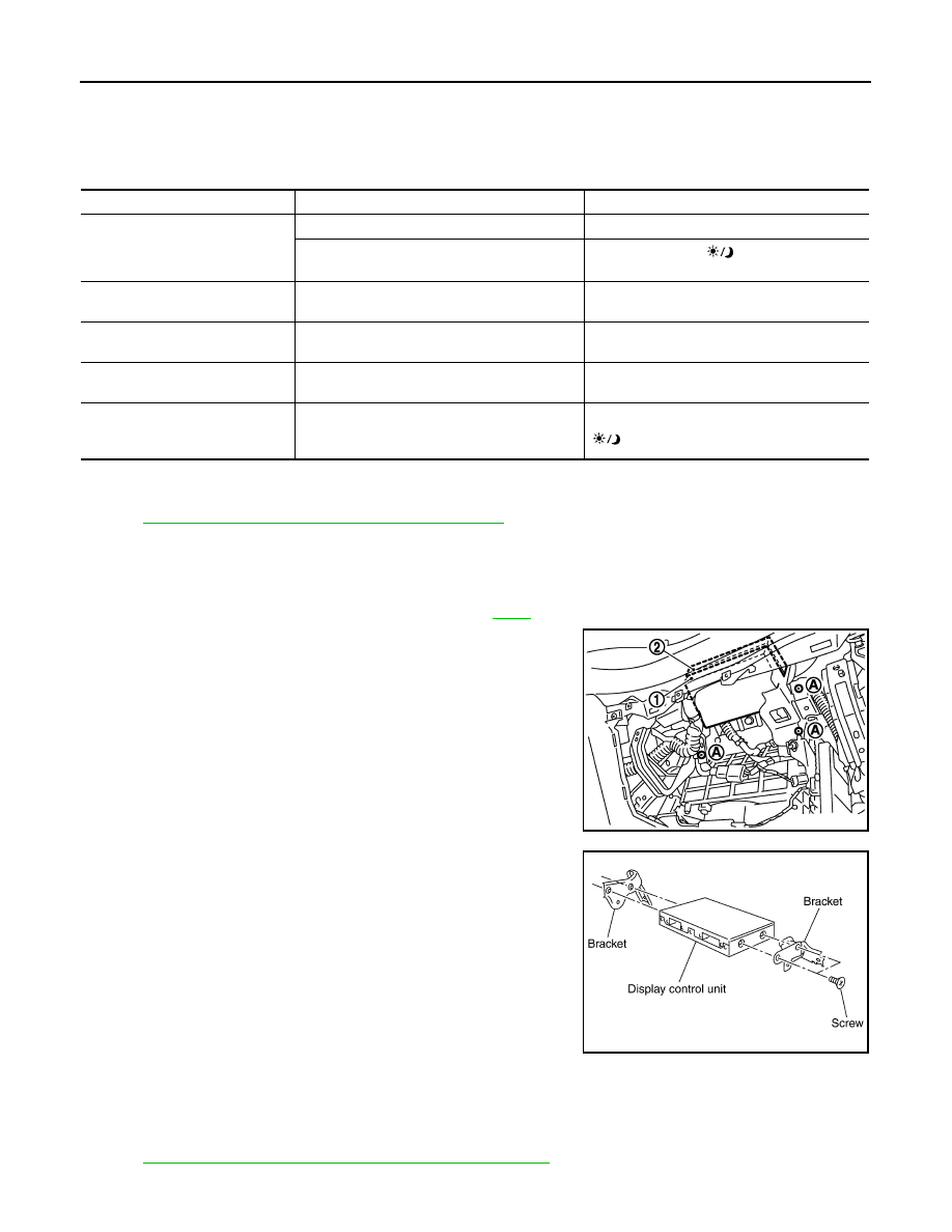
REMOVAL
1.
Remove instrument passenger lower panel. Refer to
.
2.
Remove screws (A) with power tool and remove display control
unit (1).
3.
Remove screws (4) with power tool and remove brackets.
INSTALLATION
Installation is the reverse order of removal.
Removal and Installation of A/C and AV Switch
INFOID:0000000001328738
AV-42, "Removal and Installation for A/C and AV Switch"
.
Symptom
Possible cause
Possible solution
No image is displayed.
The brightness is at the lowest setting.
Adjust the brightness of the display.
The display is turned off.
Press and hold the
button to turn on the
display.
The screen is too dim.
The movement is slow.
The temperature in the interior of the vehicle is
low.
Wait until the interior of the vehicle has warmed
up.
Some pixels in the display are
darker or brighter than others.
This condition is an inherent characteristic of liq-
uid crystal displays.
This is not a malfunction.
Some menu items cannot be se-
lected.
Some menu items become unavailable while
the vehicle is driven.
Park the vehicle in a safe location, then operate
the navigation system.
The screen does not switch to the
night screen even after turning on
the headlights.
The daytime screen was set the last time the
headlights were turned on.
Set the screen to the night screen mode using
button when turning on the headlights.
SKIB8667E
SKIA5826E
NAVIGATION SYSTEM
AV-87
< SERVICE INFORMATION >
C
D
E
F
G
H
I
J
L
M
A
B
AV
N
O
P
NAVIGATION SYSTEM
System Description
INFOID:0000000001328739
• For Navigation System operation information, refer to Navigation System Owner's Manual.
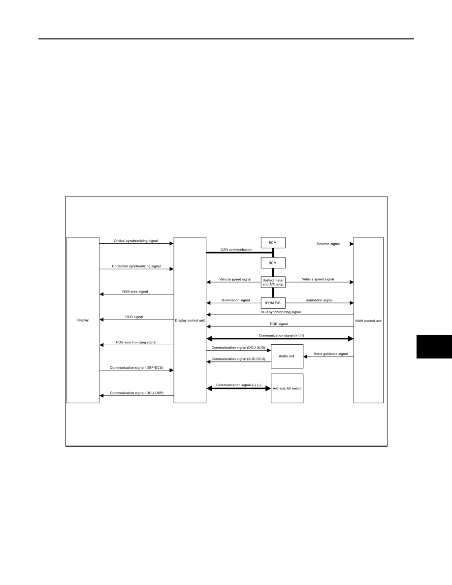
• Each control unit that comprises the system is connected with a communication circuit. It transmits/receives
data signals including request signals and response signals, and controls the system.
• The display control unit transmits/receives data signals to/from each control unit with CAN communication. It
performs an arithmetical operation on fuel information values by using data obtained from the control units,
and then displays the calculated values on the screen.
• The display control unit receives door switch signals from the BCM with CAN communication, and displays a
warning on the screen when driving over the set speed with a door half-shut.
• The display control unit receives vehicle speed signals that are transmitted from the unified meter and A/C
amp., performs an arithmetical operation on drive information values, and then displays the calculated val-
ues on the screen.
• The images displayed on the monitor screen contain NAVI control unit-generated RGB images.
• The display control unit controls image switching and image quality adjustments by communications with the
display.
NAVIGATION SYSTEM
Location Detection Principle
SKIB8652E
AV-88
< SERVICE INFORMATION >
NAVIGATION SYSTEM
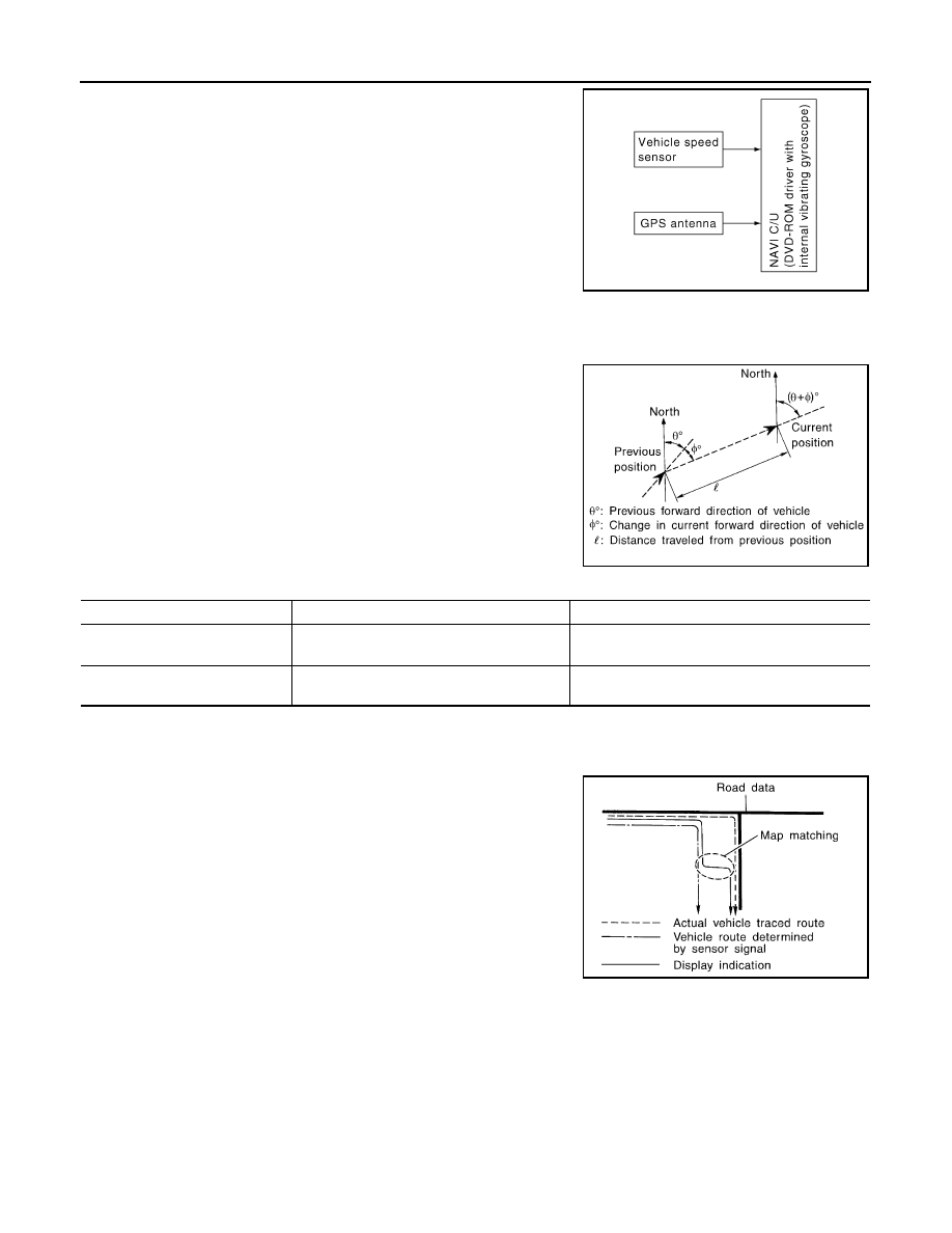
The navigation system periodically calculates the vehicle's current
position according to the following three signals:
• Travel distance of the vehicle as determined by the vehicle speed
sensor
• Turning angle of the vehicle as determined by the gyroscope
(angular velocity sensor)
• Direction of vehicle travel as determined by the GPS antenna
(GPS information)
The current position of the vehicle is then identified by comparing the
calculated vehicle position with map data read from the DVD-ROM,
which is stored in the DVD-ROM drive (map-matching), and indi-
cated on the screen as a current-location mark. More accurate data
is judged and used by comparing vehicle position detection results found by the GPS with the result by map-
matching.
The current vehicle position will be calculated by detecting the dis-
tance the vehicle moved from the previous calculation point and its
direction.
• Travel distance
Travel distance calculations are based on the vehicle speed sen-
sor input signal. Therefore, the calculation may become incorrect
as the tires wear down. To prevent this, an automatic distance cor-
rection function has been adopted.
• Travel direction
Change in the travel direction of the vehicle is calculated by a gyro-
scope (angular velocity sensor) and a GPS antenna (GPS informa-
tion). They have both advantages and disadvantages.
More accurate traveling direction is selected because priorities are set for the signals from these two devices
according to the situation.
Map-Matching
Map-matching compares a current location detected by the method
in the “Location Detection Principle” with a road map data from DVD-
ROM stored in DVD-ROM drive.
NOTE:
The road map data is based on data stored in the DVD-ROM.
The vehicle position may not be corrected under the following circumstances and after driving for a certain
time when GPS information is difficult to receive. In this case, the current-location mark on the display must be
corrected manually.
SKIB1058E
SEL684V
Type
Advantage
Disadvantage
Gyroscope (angular velocity sen-
sor)
Can detect the vehicle's turning angle quite
accurately.
Direction errors may accumulate when vehicle is
driven for long distances without stopping.
GPS antenna (GPS information)
Can detect the vehicle's travel direction
(North/South/East/West).
Correct direction cannot be detected when vehicle
speed is low.
SEL685V
NAVIGATION SYSTEM
AV-89
< SERVICE INFORMATION >
C
D
E
F
G
H
I
J
L
M
A
B
AV
N
O
P
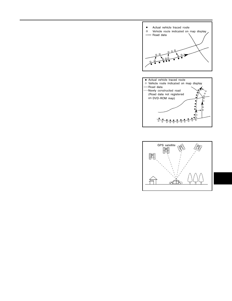
• In map-matching, alternative routes are prepared and prioritized in
addition to the road judged currently driven. Due to the distance
and/or direction error, the incorrect road may be prioritized and
current-location mark may be repositioned to the wrong road.
When two roads are running in parallel, they are judged to the
same priority. Therefore, the current-location mark may appear on
either of them alternately, depending on maneuvering of the steer-
ing wheel and configuration of the road.
• Map-matching does not function correctly when a road on which
the vehicle is driving is new and not recorded in the DVD-ROM, or
when road pattern stored in the map data and the actual road pat-
tern are different due to repair.
When driving on a road not present in the map, the map-matching
function may find another road and position the current-location
mark on it. Then, when the correct road is detected, the current-
location mark may change to it.
• Effective range for comparing the vehicle position and travel direc-
tion calculated by the distance and direction with the road data
read from the DVD-ROM is limited. Therefore, when there is an
excessive gap between current vehicle position and the position on
the map, correction by map-matching is not possible.
GPS (Global Positioning System)
GPS (Global Positioning System) was developed for and is con-
trolled by the US Department of Defense. The system utilizes GPS
satellites (NAVSTAR), sending out radio waves while flying on an
orbit around the earth at an altitude of approximately 21,000 km
(13,100 miles).
The GPS receiver calculates the vehicle's position in three dimen-
sions (latitude/longitude/altitude) according to the time lag of the
radio waves received from four or more GPS satellites (three-dimen-
sional positioning). If radio waves were received only from three
GPS satellites, the GPS receiver calculates the vehicle's position in
two dimensions (latitude/longitude), and utilize the altitude data cal-
culated previously with radio waves from four or more GPS satellites
(two-dimensional positioning).
Position correction by GPS is not available while the vehicle is stopped.
Accuracy of GPS will deteriorate under the following conditions:
• In two-dimensional positioning, GPS accuracy will deteriorate when altitude of the vehicle position changes.
• The accuracy can be even lower depending on the arrangement of the GPS satellites utilized for the posi-
tioning.
• Position detection is not possible when vehicle is in an area where radio waves from the GPS satellite do not
reach, such as in a tunnel, parking lot in a building, and under an elevated highway. Radio waves from the
GPS satellites may not be received when some object is located over the GPS antenna.
NOTE:
• Even a high-precision three dimensional positioning, the detection result has an error about 10 m (30ft).
• Because the signals of GPS satellite is controlled by the Tracking and Control Center in the United States,
the accuracy may be degraded lower intentionally or the radio waves may stop.
Component Description
INFOID:0000000001328740
NAVI CONTROL UNIT
SEL686V
SKIA0613E
SEL526V
Нет комментариевНе стесняйтесь поделиться с нами вашим ценным мнением.
Текст