Infiniti FX35 / FX45. Manual — part 156
AV-78
< SERVICE INFORMATION >
INTEGRATED DISPLAY SYSTEM
4.
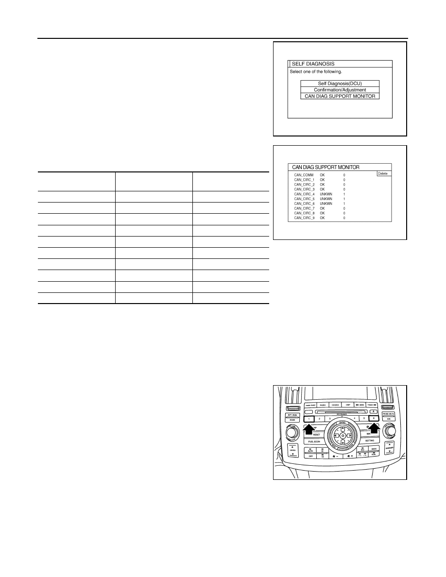
The initial trouble diagnosis screen will be shown, and items
“Self Diagnosis (DCU)”, “Confirmation/Adjustment” and “CAN
DIAG SUPPORT MONITOR” will become selective.
5.
Select “CAN DIAG SUPPORT MONITOR”.
6.
The transmitting/receiving of CAN communication can be moni-
tored.
NOTE:
Counter shows the status of CAN communication.
A/C and AV Switch Self-Diagnosis Function
INFOID:0000000001328726
Performing self-diagnosis makes it possible to check operation of A/C and AV switch indicator (LED) and other
switch.
STARTING THE SELF-DIAGNOSIS MODE
1.
Turn ignition switch from OFF to ACC.
2.
Within 10 seconds press and hold the switches “1” and “6”
simultaneously for 3 seconds.
DIAGNOSIS FUNCTION
The following are checked:
• All the indicators (LED) in the A/C and AV switch.
• Continuity of the switches by sounding the buzzer when the A/C and AV switch and audio steering wheel
switch is pressed.
• Continuity of harness between A/C and AV switch and audio steering wheel switch.
NOTE:
SKIB7871E
Item
Content
Error counter
(Reference value)
CAN_COMM
OK/NG
0 - 50
CAN_CIRC_1
OK/UNKWN
0 - 50
CAN_CIRC_2
OK/UNKWN
0 - 50
CAN_CIRC_3
OK/UNKWN
0 - 50
CAN_CIRC_4
OK/UNKWN
0 - 50
CAN_CIRC_5
OK/UNKWN
0 - 50
CAN_CIRC_6
OK/UNKWN
0 - 50
CAN_CIRC_7
OK/UNKWN
0 - 50
CAN_CIRC_8
OK/UNKWN
0 - 50
CAN_CIRC_9
OK/UNKWN
0 - 50
SKIA4288E
SKIB8744E
INTEGRATED DISPLAY SYSTEM
AV-79
< SERVICE INFORMATION >
C
D
E
F
G
H
I
J
L
M
A
B
AV
N
O
P
Rear window defogger switch operation is not checked (No beep sound even under normal status).
EXITING THE SELF-DIAGNOSIS MODE
• Turn ignition switch OFF.
CAN Communication Check
INFOID:0000000001328727
1.
CHECK MONITOR DESCRIPTION
1.
Start self-diagnosis of DCU. Refer to
AV-73, "Self-Diagnosis Mode (DCU)"
.
2.
Select “CAN DIAG SUPPORT MONITOR”. Refer to
"CAN Diagnostic Support Monitor"
3.
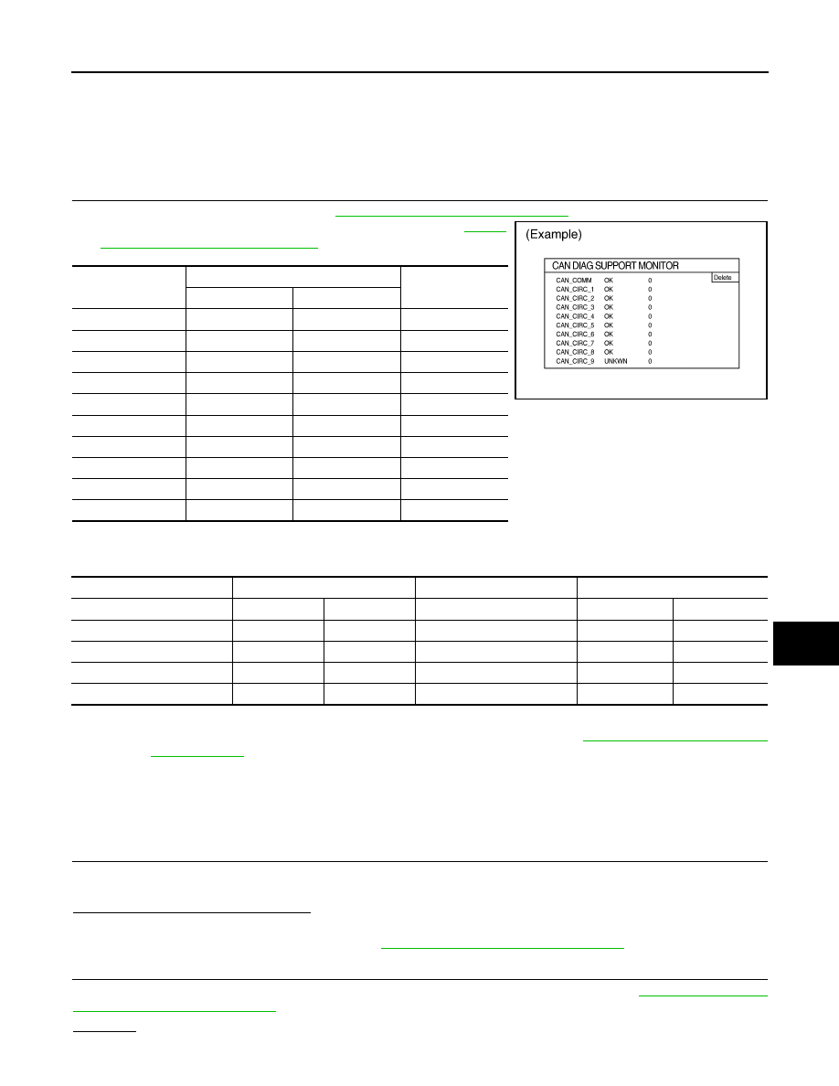
Record each item display description (OK/NG/UNKWN) displayed on the following CAN DIAG SUPPORT
MONITOR Check Sheet.
CAN DIAG SUPPORT MONITOR Check Sheet
>> After filling in CAN DIAG SUPPORT MONITOR Check Sheet, Go to
Unable to Operate System with A/C and AV Switch
INFOID:0000000001328728
Symptom: Unable to operate A/C system and audio system with A/C and AV switch. (Unable to start self-diag-
nosis.)
1.
CHECK CONDITION
1.
Turn ignition switch ON.
2.
Check if an image is displayed on the screen.
Is an image displayed on the screen?
YES
>> GO TO 2.
NO
>> Repair malfunctioning part. Refer to
AV-80, "All Images Are Not Displayed"
2.
SELF-DIAGNOSIS OF A/C AND AV SWITCH
Start self-diagnosis of A/C and AV switch, and check the self-diagnosis result. Refer to
Switch Self-Diagnosis Function"
.
OK or NG
Item
content
Error counter
(Reference value)
Normal condition
Error (Example)
CAN_COMM
OK
NG
0 - 50
CAN_CIRC_1
OK
UNKWN
0 - 50
CAN_CIRC_2
OK
UNKWN
0 - 50
CAN_CIRC_3
OK
UNKWN
0 - 50
CAN_CIRC_4
OK
UNKWN
0 - 50
CAN_CIRC_5
OK
UNKWN
0 - 50
CAN_CIRC_6
OK
UNKWN
0 - 50
CAN_CIRC_7
OK
UNKWN
0 - 50
CAN_CIRC_8
OK
UNKWN
0 - 50
CAN_CIRC_9
UNKWN
UNKWN
0 - 50
PKIB6080E
Diagnosis item
Screen display
Diagnosis item
Screen display
CAN_COMM
OK
NG
CAN_CIRC_5
OK
UNKWN
CAN_CIRC_1
OK
UNKWN
CAN_CIRC_6
OK
UNKWN
CAN_CIRC_2
OK
UNKWN
CAN_CIRC_7
OK
UNKWN
CAN_CIRC_3
OK
UNKWN
CAN_CIRC_8
OK
UNKWN
CAN_CIRC_4
OK
UNKWN
CAN_CIRC_9
OK
UNKWN
AV-80
< SERVICE INFORMATION >
INTEGRATED DISPLAY SYSTEM
OK
>> GO TO 4.
NG
>> GO TO 3.
3.
CHECK A/C AND AV SWITCH POWER SUPPLY AND GROUND CIRCUIT
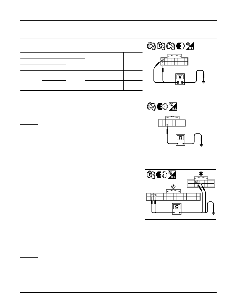
1.
Check voltage between A/C and AV switch harness connector
terminals and ground.
2.
Turn ignition switch OFF.
3.
Disconnect A/C and AV switch connector.
4.
Check continuity between A/C and AV switch harness connector
M64 terminal 5 and ground.
OK or NG
OK
>> Replace A/C and AV switch.
NG
>> Repair harness or connector.
4.
CHECK HARNESS
1.
Turn ignition switch OFF.
2.
Disconnect display control unit and A/C and AV switch connectors.
3.
Check continuity between display control unit harness connector
(A) M76 terminals 28, 30 and A/C and AV switch harness con-
nector (B) M64 terminals 6, 8.
4.
Check continuity between display control unit harness connector
(A) M76 terminals 28, 30 and ground.
OK or NG
OK
>> GO TO 5.
NG
>> Repair harness or connector.
5.
CHECK A/C AND AV SWITCH AND DISPLAY CONTROL UNIT
1.
Replace A/C and AV switch or display control unit.
2.
Make sure that A/C system and audio system can be operated by A/C and AV switch.
OK or NG
OK
>> INSPECTION END
NG
>> Replace the other unit.
All Images Are Not Displayed
INFOID:0000000001328729
Symptom: RGB image is not displayed.
1.
CHECK CONDITION
Terminals
OFF
ACC
ON
(+)
(–)
Connector
Terminal
M64
1
Ground
Battery
voltage
Battery
voltage
Battery
voltage
2
0 V
Battery
voltage
Battery
voltage
5 – Ground
: Continuity should exist.
SKIB7836E
SKIB7837E
28 – 6
: Continuity should exist.
30 – 8
: Continuity should exist.
28, 30 – Ground
: Continuity should not exist.
SKIB7838E
INTEGRATED DISPLAY SYSTEM
AV-81
< SERVICE INFORMATION >
C
D
E
F
G
H
I
J
L
M
A
B
AV
N
O
P
When operating audio and air conditioner, make sure that they operate correctly.
Do audio and air conditioner operate normally?
YES
>> GO TO 2.
NO
>> GO TO 5.
2.
CHECK DISPLAY GROUND CIRCUIT
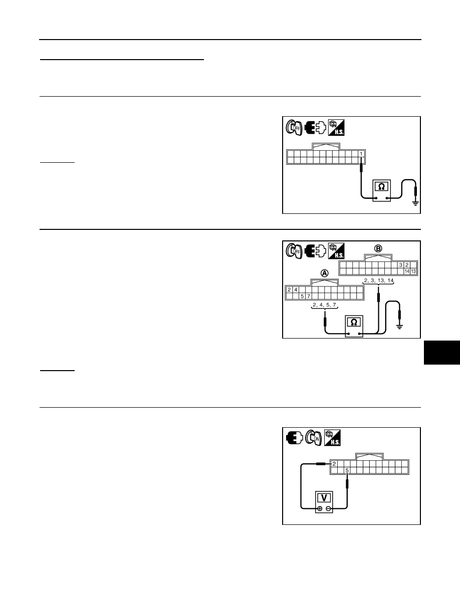
1.
Turn ignition switch OFF.
2.
Disconnect display connector.
3.
Check continuity between display harness connector M63 termi-
nal 1 and ground.
OK or NG
OK
>> GO TO 3.
NG
>> Repair harness or connector.
3.
CHECK HARNESS
1.
Disconnect display control unit connector.
2.
Check continuity between display control unit harness connector
(A) M75 terminals 2, 4, 5, 7 and display harness connector (B)
M63 terminals 2, 3, 13, 14.
3.
Check continuity between display control unit harness connector
(A) M75 terminals 2, 4 and ground.
OK or NG
OK
>> GO TO 4.
NG
>> Repair harness or connector.
4.
CHECK DISPLAY POWER SUPPLY AND GROUND CIRCUIT (INVERTER AND SIGNAL)
1.
Connect display control unit and display connectors.
2.
Turn ignition switch ON.
3.
Check voltage between display control unit harness connector
M75 terminals 2 and 5.
1 – Ground
: Continuity should exist.
SKIB7839E
2 – 2
: Continuity should exist.
4 – 3
: Continuity should exist.
5 – 13
: Continuity should exist.
7 – 14
: Continuity should exist.
2, 4 – Ground
: Continuity should not exist.
SKIB7840E
2 – 5
: Approx. 9 V
SKIB7841E
Нет комментариевНе стесняйтесь поделиться с нами вашим ценным мнением.
Текст