Infiniti FX35 / FX45. Manual — part 157
AV-82
< SERVICE INFORMATION >
INTEGRATED DISPLAY SYSTEM
4.
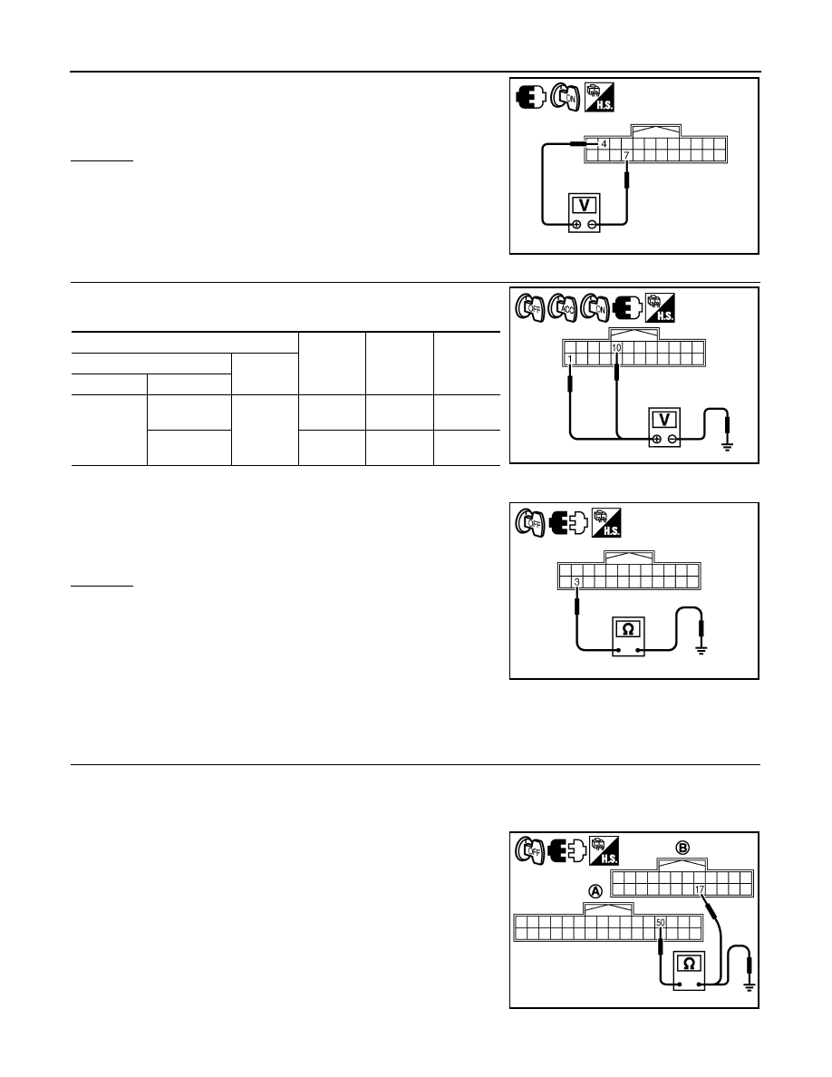
Check voltage between display control unit harness connector
M75 terminals 4 and 7.
OK or NG
OK
>> Replace display.
NG
>> Replace display control unit.
5.
CHECK DISPLAY CONTROL UNIT POWER SUPPLY AND GROUND CIRCUIT
1.
Check voltage between display control unit harness connector
terminals and ground.
2.
Turn ignition switch OFF.
3.
Disconnect display control unit connector.
4.
Check continuity between display control unit harness connector
M75 terminal 3 and ground.
OK or NG
OK
>> Replace display control unit.
NG
>> Repair harness or connector.
Tint Is Strange for the RGB Image
INFOID:0000000001328730
Symptom: Tint of all RGB images is strange.
1.
CHECK HARNESS
1.
Turn ignition switch OFF.
2.
Disconnect display control unit and display connectors.
3.
Check the malfunctioning circuit according to the symptoms.
• Light blue (Cyan) tinged screen
Check continuity between display control unit harness connector
(A) M76 terminal 50 and display harness connector (B) M63 termi-
nal 17.
Check continuity between display control unit harness connector
(A) M76 terminal 50 and ground.
4 – 7
: Approx. 9 V
SKIB7842E
Terminals
OFF
ACC
ON
(+)
(–)
Connector
Terminal
M75
1
Ground
Battery
voltage
Battery
voltage
Battery
voltage
10
0 V
Battery
voltage
Battery
voltage
3 – Ground
: Continuity should exist.
SKIB7843E
SKIB7844E
50 – 17
: Continuity should exist.
50 – Ground
: Continuity should not exist.
SKIB7853E
INTEGRATED DISPLAY SYSTEM
AV-83
< SERVICE INFORMATION >
C
D
E
F
G
H
I
J
L
M
A
B
AV
N
O
P
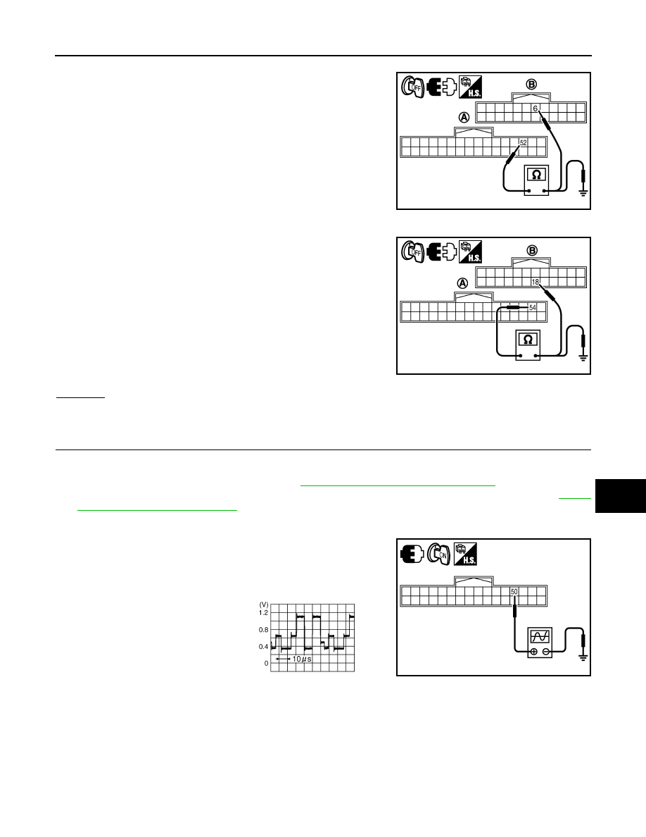
• Purple (Magenta) tinged screen
Check continuity between display control unit harness connector
(A) M76 terminal 52 and display harness connector (B) M63 termi-
nal 6.
Check continuity between display control unit harness connector
(A) M76 terminal 52 and ground.
• Yellow tinged screen
Check continuity between display control unit harness connector
(A) M76 terminal 54 and display harness connector (B) M63 termi-
nal 18.
Check continuity between display control unit harness connector
(A) M76 terminal 54 and ground.
OK or NG
OK
>> GO TO 2.
NG
>> Repair harness or connector.
2.
CHECK RGB SIGNAL
1.
Connect display control unit and display connectors.
2.
Turn ignition switch ON.
3.
Start Confirmation/Adjustment mode. Refer to
AV-75, "Confirmation/Adjustment Mode"
4.
Display color bar by selecting “Display Color Spectrum Bar” on Display Diagnosis screen. Refer to
"Confirmation/Adjustment Mode"
5.
Check the malfunctioning circuit according to the symptoms.
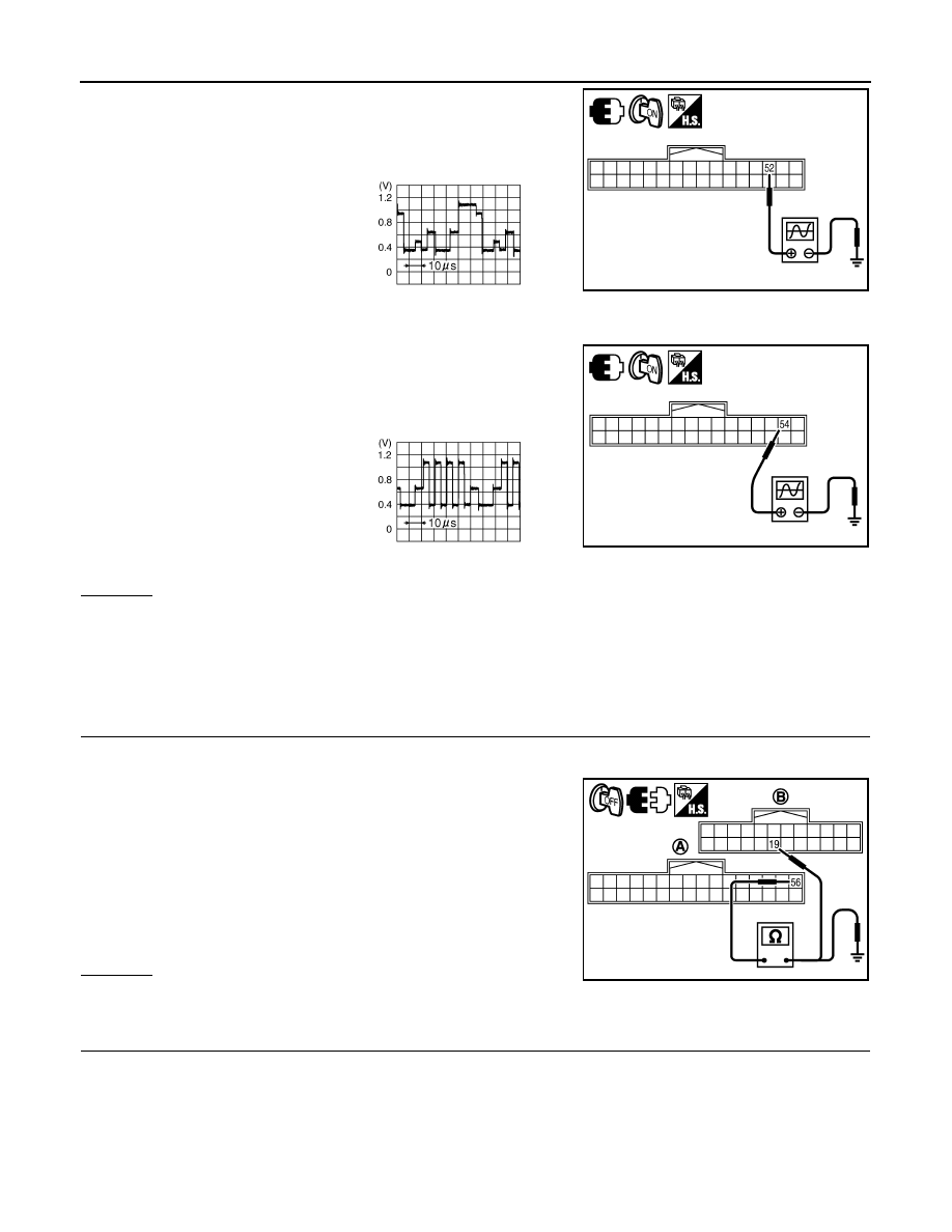
• Light blue (Cyan) tinged screen
Check voltage waveform between display control unit harness con-
nector M76 terminal 50 and ground with CONSULT-III or oscillo-
scope.
• Purple (Magenta) tinged screen
52 – 6
: Continuity should exist.
52 – Ground
: Continuity should not exist.
SKIB7854E
54 – 18
: Continuity should exist.
54 – Ground
: Continuity should not exist.
SKIB7855E
50 – Ground:
SKIB7856E
SKIB7769E
AV-84
< SERVICE INFORMATION >
INTEGRATED DISPLAY SYSTEM
Check voltage waveform between display control unit harness con-
nector M76 terminal 52 and ground with CONSULT-III or oscillo-
scope.
• Yellow tinged screen
Check voltage waveform between display control unit harness con-
nector M76 terminal 54 and ground with CONSULT-III or oscillo-
scope.
OK or NG
OK
>> Replace display.
NG
>> Replace display control unit.
RGB Image Is Rolling
INFOID:0000000001328731
Symptom: RGB image is rolling.
1.
CHECK HARNESS
1.
Turn ignition switch OFF.
2.
Disconnect display control unit and display connectors.
3.
Check continuity between display control unit harness connector
(A) M76 terminal 56 and display harness connector (B) M63 ter-
minal 19.
4.
Check continuity between display control unit harness connector
(A) M76 terminal 56 and ground.
OK or NG
OK
>> GO TO 2.
NG
>> Repair harness or connector.
2.
CHECK RGB SYNCHRONIZING SIGNAL
1.
Connect display control unit and display connectors.
2.
Turn ignition switch ON.
52 – Ground:
SKIB7857E
SKIB7770E
54 – Ground:
SKIB7858E
SKIB7771E
56 – 19
: Continuity should exist.
56 – Ground
: Continuity should not exist.
SKIB7863E
INTEGRATED DISPLAY SYSTEM
AV-85
< SERVICE INFORMATION >
C
D
E
F
G
H
I
J
L
M
A
B
AV
N
O
P
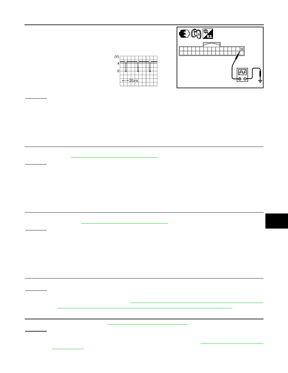
3.
When displaying RGB image, check voltage waveform between
display control unit harness connector M76 terminal 56 and
ground with CONSULT-III or oscilloscope.
OK or NG
OK
>> Replace display.
NG
>> Replace display control unit.
Value for All Item in the TRIP Screen Do Not Change
INFOID:0000000001328732
Symptom: Values for items, “Elapsed Time”, “Driving Distance” and “Average Speed” in the TRIP screen do
not change. FUEL ECONOMY screen is not displayed when pressing “TRIP” button.
1.
CHECK DISPLAY CONTROL UNIT IGNITION SIGNAL
Select “Vehicle Signals” in Confirmation/Adjustment mode, and check the ignition signal inputting to display
control unit. Refer to
AV-75, "Confirmation/Adjustment Mode"
OK or NG
OK
>> Replace display control unit.
NG
>> Check display control unit ignition signal circuit, and repair malfunctioning part.
Value for Item, "Driving Distance" and "Average Speed" Do Not Change
INFOID:0000000001328733
Symptom: Values for Items, "Driving Distance" and "Average Speed" do not change. (The Value for "Elapsed
Time" Changes.)
1.
CHECK DISPLAY CONTROL UNIT VEHICLE SPEED SIGNAL
Select “Vehicle Signals” in Confirmation/Adjustment mode, and check the vehicle speed signal inputting to dis-
play control unit. Refer to
AV-75, "Confirmation/Adjustment Mode"
.
OK or NG
OK
>> Replace display control unit.
NG
>> Check display control unit vehicle speed signal circuit, and repair malfunctioning part.
Value for All Item in the FUEL ECONOMY Screen Do Not Change
INFOID:0000000001328734
Symptom: Values for items, “Average Fuel Economy” and “Distance to Empty” in the FUEL ECONOMY screen
do not change.
1.
CHECK CONDITION
Check if values for all items in the TRIP screen change properly.
OK or NG
OK
>> GO TO 2.
NG
>> Repair malfunctioning part. Refer to
AV-85, "Value for All Item in the TRIP Screen Do Not Change"
or
AV-85, "Value for Item, "Driving Distance" and "Average Speed" Do Not Change"
.
2.
CHECK CAN COMMUNICATION
Check CAN communication. Refer to
AV-79, "CAN Communication Check"
OK or NG
OK
>> Replace display control unit.
NG
>> After filling out CAN DIAG SUPPORT MONITOR check sheet, Go to
56 – Ground:
SKIB7864E
SKIB3603E
Нет комментариевНе стесняйтесь поделиться с нами вашим ценным мнением.
Текст