Infiniti FX35 / FX45. Manual — part 924
SE-54
< SERVICE INFORMATION >
AUTOMATIC DRIVE POSITIONER
2.
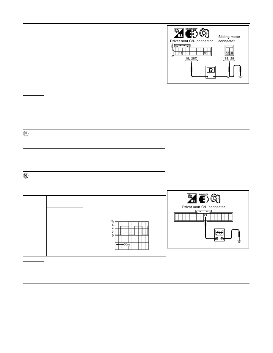
Check continuity between driver seat control unit connector
B152 terminals 18, 28C and sliding motor connector B161 termi-
nals 18, 28.
3.
Check continuity between driver seat control unit connector
B152 terminals 18, 28C and ground.
OK or NG
OK
>> Replace sliding motor.
NG
>> Repair or replace harness between driver seat control unit and sliding motor.
Check Reclining Sensor Circuit
INFOID:0000000001328120
1.
CHECK FUNCTION
With CONSULT-III
Check operation with “RECLINING PULSE” on the DATA MONITOR to make sure the pulse changes.
Without CONSULT-III
1.
Turn ignition switch OFF.
2.
Check signal between driver seat control unit connector and ground, with oscilloscope.
OK or NG
OK
>> Reclining sensor circuit is OK.
NG
>> GO TO 2.
2.
CHECK RECLINING SENSOR HARNESS CONTINUITY
1.
Disconnect driver seat control unit connector and reclining motor connector.
18 (G/L) – 18 (G/L)
: Continuity should exist.
28C (B/W) – 28 (B/W)
: Continuity should exist.
18 (G/L) – Ground
: Continuity should not exist.
28C (B/W) – Ground
: Continuity should not exist.
PIIA6106E
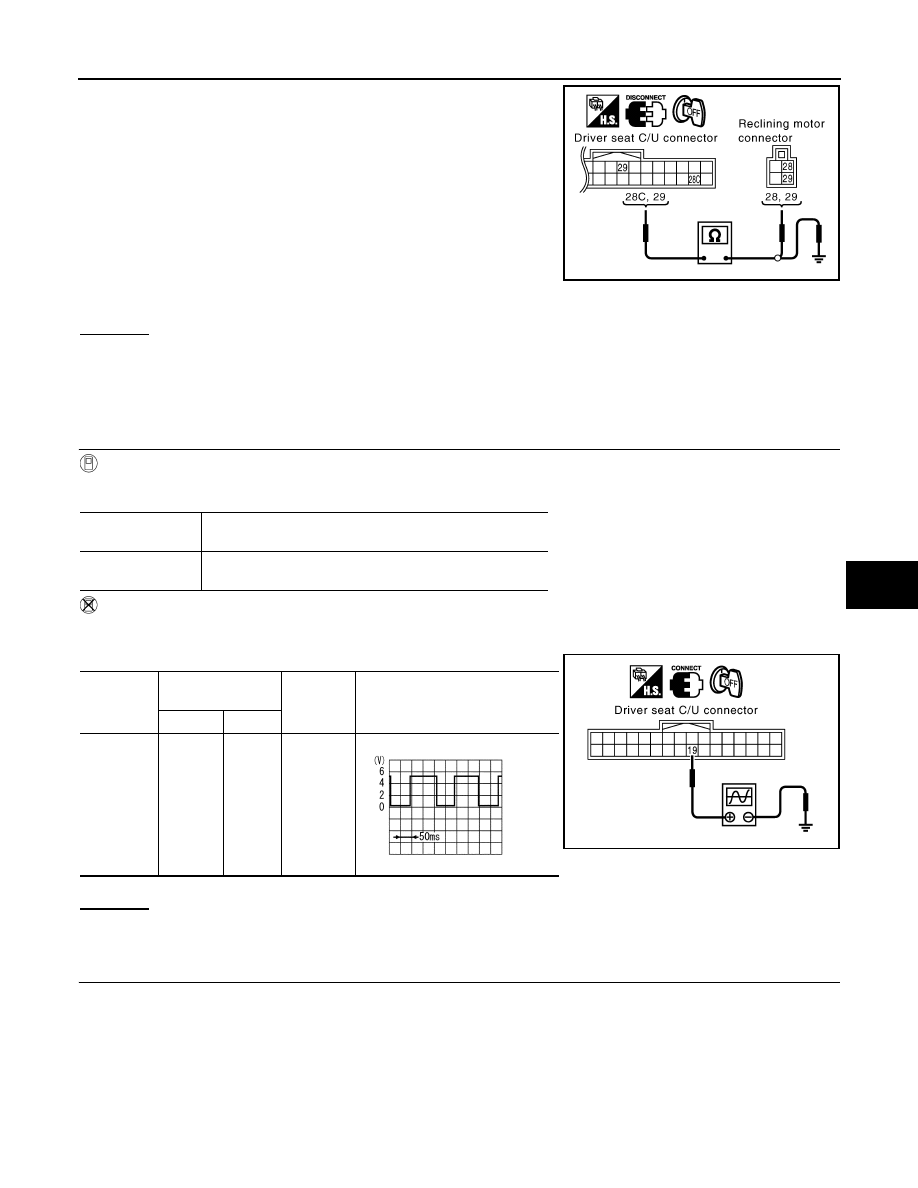
Monitor item [PO-
ERATION or UNIT]
Contents
RECLN PULSE
The seat reclining position (pulse) judged from the reclining
sensor is displayed
Connector
Terminals
(Wire color)
Condition
Signal
(Reference value)
(+)
(–)
B152
29 (G)
Ground
Reclining
motor op-
eration
PIIA6107E
SIIA0692J
AUTOMATIC DRIVE POSITIONER
SE-55
< SERVICE INFORMATION >
C
D
E
F
G
H
J
K
L
M
A
B
SE
N
O
P
2.
Check continuity between driver seat control unit connector
B152 terminals 28C, 29 and reclining motor connector B166 ter-
minals 28, 29.
3.
Check continuity between driver seat control unit connector
B152 terminals 28C, 29 and ground.
OK or NG
OK
>> Replace reclining motor.
NG
>> Repair or replace harness between connectors driver seat control unit and reclining motor.
Check Front Lifting Sensor Circuit
INFOID:0000000001328121
1.
CHECK FUNCTION
With CONSULT-III
Check operation with “LIFT FR PULSE” on the DATA MONITOR to make sure the pulse changes.
Without CONSULT-III
1.
Turn ignition switch OFF.
2.
Check signal between driver seat control unit connector and ground, with oscilloscope.
OK or NG
OK
>> Front lifting sensor circuit is OK.
NG
>> GO TO 2.
2.
CHECK FRONT LIFTING SENSOR HARNESS CONTINUITY
1.
Disconnect driver seat control unit connector and front lifting motor connector.
28C (B/W) – 28 (B/W)
: Continuity should exist.
29 (G) – 29 (G)
: Continuity should exist.
28C (B/W) – Ground
: Continuity should not exist.
29 (G) – Ground
: Continuity should not exist.
PIIA6108E
Monitor item [OP-
ERATION or UNIT]
Contents
LIFT FR PULSE
The front lifting position (pulse) judged from the front lifting
sensor is displayed
Connector
Terminals
(Wire color)
Condition
Signal
(Reference value)
(+)
(–)
B152
19 (G/R)
Ground
Front lift-
ing motor
operation
PIIA6109E
SIIA0691J

SE-56
< SERVICE INFORMATION >
AUTOMATIC DRIVE POSITIONER
2.
Check continuity between driver seat control unit connector
B152 terminals 19, 28C and front lifting motor connector B164
terminals 19, 28A.
3.
Check continuity between driver seat control unit connector
B152 terminals 19, 28C and ground.
OK or NG
OK
>> Replace front lifting motor.
NG
>> Repair or replace harness between driver seat control unit and front lifting motor.
Check Rear Lifting Sensor Circuit
INFOID:0000000001328122
1.
CHECK REAR LIFTING SENSOR INPUT/OUTPUT SIGNAL
With CONSULT-III
Check operation with “LIFT RP PULSE” on the DATA MONITOR to make sure pulse changes.
Without CONSULT-III
1.
Turn ignition switch OFF.
2.
Check signal between driver seat control unit connector ground, with oscilloscope.
OK or NG
OK
>> Rear lifting sensor circuit is OK.
NG
>> GO TO 2.
2.
CHECK REAR LIFTING SENSOR HARNESS CONTINUITY
1.
Disconnect driver seat control unit connector and rear lifting motor connector.
19 (G/R) – 19 (G/R)
: Continuity should exist.
28C (B/W) – 28A (B/W)
: Continuity should exist.
19 (G/R) – Ground
: Continuity should not exist.
28C (B/W) – Ground
: Continuity should not exist.
PIIA6110E
Monitor item [OP-
ERATION or UNIT
Contents
LIFT RR PULSE
The rear lifting position (pulse) judged from the rear lifting
sensor is displayed.
Connector
Terminals
(Wire color)
Condition
Signal
(Reference value)
(+)
(–)
B152
30 (R/W)
Ground
Rear lift-
ing motor
operation
PIIA6111E
SIIA0693J
AUTOMATIC DRIVE POSITIONER
SE-57
< SERVICE INFORMATION >
C
D
E
F
G
H
J
K
L
M
A
B
SE
N
O
P
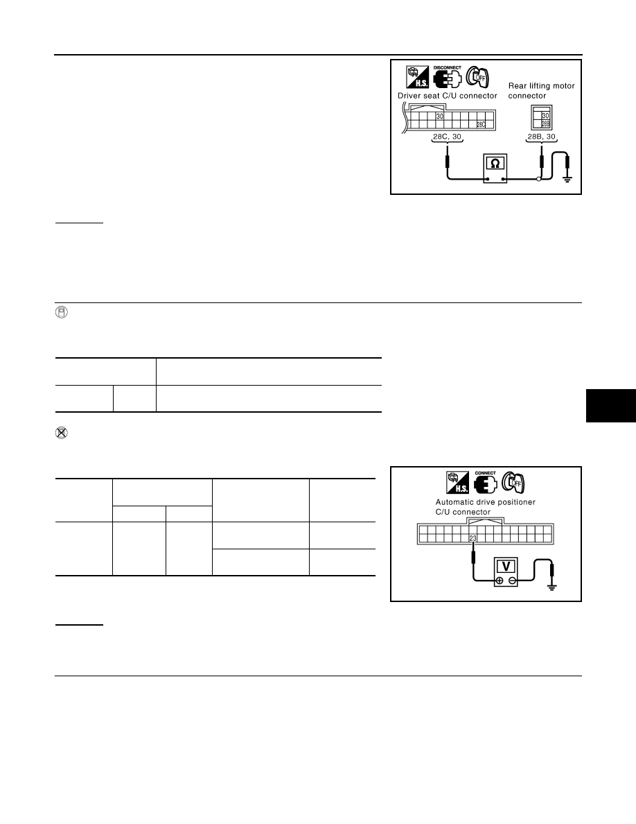
2.
Check continuity between driver seat control unit connector
B152 terminals 28C, 30 and rear lifting motor connector B162
terminals 28B, 30.
3.
Check continuity between driver seat control unit connector
B152 terminals 28C, 30 and ground.
OK or NG
OK
>> Replace rear lifting motor.
NG
>> Repair or replace harness between driver seat control unit and rear lifting motor.
Check Telescopic Sensor Circuit
INFOID:0000000001328123
1.
CHECK FUNCTION
With CONSULT-III
Operate the telescopic switch with “TELESCO SEN” on the DATA MONITOR to make sure the voltage
changes.
Without CONSULT-III
1.
Turn ignition switch OFF.
2.
Check voltage between automatic drive positioner control unit connector and ground.
OK or NG
OK
>> Telescopic sensor circuit is OK.
NG
>> GO TO 2.
2.
CHECK HARNESS CONTINUITY
1.
Disconnect automatic drive positioner control unit connector and tilt sensor and telescopic sensor connec-
tor.
28C (B/W) – 28B (B/W)
: Continuity should exist.
30 (R/W) – 30 (R/W)
: Continuity should exist.
28C (B/W) – Ground
: Continuity should not exist.
30 (R/W) – Ground
: Continuity should not exist.
PIIA6112E
Monitor item
[OPERATION or UNIT]
Contents
TELESCO
SEN
“V”
The telescoping position (voltage) judged from the tele-
scoping sensor signal is displayed.
Connector
Terminals
(Wire color)
Condition
Voltage (V)
(Approx.)
(+)
(–)
M49
23 (Y/B)
Ground
Telescopic
top position
1
Telescopic
bottom position
4
PIIA5070E
Нет комментариевНе стесняйтесь поделиться с нами вашим ценным мнением.
Текст