Infiniti FX35 / FX45. Manual — part 925
SE-58
< SERVICE INFORMATION >
AUTOMATIC DRIVE POSITIONER
2.
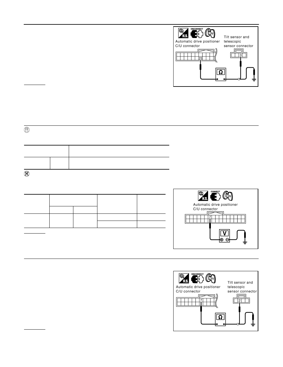
Check continuity harness between automatic drive positioner
control unit connector M49 terminals 23 and tilt sensor and tele-
scopic sensor connector M28 terminals 3.
3.
Check continuity harness between automatic drive positioner
control unit connector M49 terminals 23 and ground.
OK or NG
OK
>> Replace tilt sensor and telescopic sensor.
NG
>> Repair or replace harness between automatic drive positioner control unit and tilt sensor and tele-
scopic sensor.
Check Tilt Sensor Circuit
INFOID:0000000001328124
1.
CHECK TILT SENSOR
With CONSULT-III
With “TILT SEN” on the DATA MONITOR, operate the tilt switch to make sure voltage changes.
Without CONSULT-III
1.
Turn ignition switch OFF.
2.
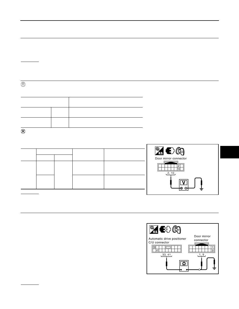
Check voltage between automatic drive positioner control unit connector and ground.
OK or NG
OK
>> Tilt sensor circuit is OK.
NG
>> GO TO 2.
2.
CHECK HARNESS
1.
Disconnect automatic drive positioner control unit connector and tilt sensor and telescopic sensor connec-
tor.
2.
Check continuity harness between automatic drive positioner
control unit connector M49 terminals 7 and tilt sensor and tele-
scopic sensor connector M28 terminals 2.
3.
Check continuity harness between automatic drive positioner
control unit connector M49 terminals 7 and ground.
OK or NG
OK
>> Replace tilt sensor and telescopic sensor.
NG
>> Repair or replace harness between automatic drive positioner control unit and tilt sensor and tele-
scopic sensor.
23 (Y/B) – 3 (Y/B)
: Continuity should exist.
23 (Y/B) – Ground
: Continuity should not exist.
PIIA5079E
Monitor item
[OPERATION or UNIT]
Contents
TILT SEN
“V”
The tilt position (voltage) judged from the tilt sensor sig-
nal is displayed.
Connector
Terminals
(Wire color)
Condition
Voltage (V)
(Approx.)
(+)
(–)
M49
7 (Y/R)
Ground
Tilt top position
2
Tilt bottom position
4
PIIA5069E
7 (Y/R) – 2 (Y/R)
: Continuity should exist.
7 (Y/R) – Ground
: Continuity should not exist.
PIIA5080E
AUTOMATIC DRIVE POSITIONER
SE-59
< SERVICE INFORMATION >
C
D
E
F
G
H
J
K
L
M
A
B
SE
N
O
P
Check Driver Side Mirror Sensor Circuit
INFOID:0000000001328125
1.
CHECK DOOR MIRROR FUNCTION
Check the following.
Operation malfunction in memory control
NOTE:
If a door mirror face position is set to an implausible angle, the set position may not be reproduced.
OK or NG
OK
>> GO TO 2.
NG
>> Repair the malfunctioning parts, and check the symptom again.
2.
CHECK MIRROR SENSOR INSPECTION
With CONSULT-III
Make sure “ON” is displayed on “MIR/SE LH R–L, MIR/SE LH U–D” in the DATA MONITOR.
Without CONSULT-III
1.
Turn ignition switch to ACC position.
2.
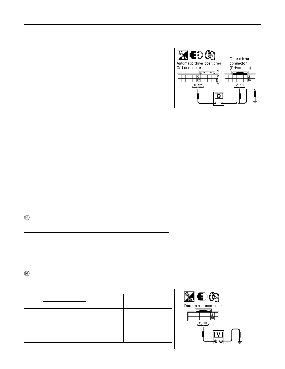
Check voltage between door mirror (driver side) connector and ground.
OK or NG
OK
>> Driver side mirror sensor circuit is OK.
NG
>> GO TO 3.
3.
CHECK HARNESS CONTINUITY 1
1.
Turn ignition switch OFF.
2.
Disconnect automatic drive positioner control unit and door mirror (driver side) connector.
3.
Check continuity between automatic drive positioner control unit
connector M50 terminals 33, 41 and door mirror (driver side)
connector D2 terminals 1, 9.
4.
Check continuity between automatic drive positioner control unit
connector M49 terminals 33, 41 and ground.
OK or NG
OK
>> GO TO 3.
Monitor item
[OPERATION or UNIT]
Contents
MIR/SE LH R–L
“V”
Voltage output from LH door mirror sensor
(LH/RH) is displayed.
MIR/SE LH U–D
“V”
Voltage output from LH door mirror sensor
(UP/DOWN) is displayed.
Con-
nector
Terminals (Wire color)
Condition
Voltage (V)
(Approx,)
(+)
(–)
D2
2 (W)
Ground
When motor is
UP or DOWN
operation
Changes between
3 (close to perk) –
1 (close to valley)
10 (LG)
When motor is
LEFT or RIGHT op-
eration
Changes between
3 (close to right edge) –
1 (close to left edge)
PIIB8585E
33 (G/W) – 1 (OR)
: Continuity should exist.
41 (B/Y) – 9 (BR)
: Continuity should exist.
33 (G/W) – Ground
: Continuity should not exist.
41 (B/Y) – Ground
: Continuity should not exist.
PIIB8586E
SE-60
< SERVICE INFORMATION >
AUTOMATIC DRIVE POSITIONER
NG
>> Repair or replace harness between automatic drive positioner control unit and door mirror (driver
side).
4.
CHECK HARNESS CONTINUITY 2
1.
Check continuity between automatic drive positioner control unit
connector M49 terminal 6, 22 and door mirror (driver side) con-
nector D2 terminal 2, 10.
2.
Check continuity between automatic drive positioner control unit
connector M49 terminal 6, 22 and ground.
OK or NG
OK
>> Check the condition of the harness and connector.
NG
>> Repair or replace harness between automatic drive positioner control unit and door mirror (driver
side).
Check Passenger Side Mirror Sensor Circuit
INFOID:0000000001328126
1.
CHECK DOOR MIRROR FUNCTION
Check the following.
Operation malfunction in memory control
NOTE:
If a door mirror face position is set to an implausible angle, the set position may not be reproduced.
OK or NG
OK
>> GO TO 2.
NG
>> Repair the malfunctioning parts, and check the symptom again.
2.
CHECK MIRROR SENSOR INSPECTION
With CONSULT-III
Make sure “ON” is displayed on “MIR/SE RH R–L, MIR/SE RH U–D” in the DATA MONITOR.
Without CONSULT-III
1.
Turn ignition switch to ACC position.
2.
Check voltage between door mirror (passenger side) connector and ground.
OK or NG
OK
>> Passenger side mirror sensor circuit is OK.
6 (P/L) – 2 (W)
: Continuity should exist.
22 (L/Y) – 10 (LG)
: Continuity should exist.
6 (P/L) – Ground
: Continuity should not exist.
22 (L/Y) – Ground
: Continuity should not exist.
PIIB8584E
Monitor item
[OPERATION or UNIT]
Contents
MIR/SE RH R–L
“V”
Voltage output from RH door mirror sensor
(LH/RH) is displayed.
MIR/SE RH U–D
“V”
Voltage output from RH door mirror sensor
(UP/DOWN) is displayed.
Con-
nector
Terminals (Wire color)
Condition
Voltage (V)
(Approx.)
(+)
(–)
D32
2 (LG)
Ground
When motor is
UP or DOWN
operation
Changes between
3 (close to perk) –
1 (close to valley)
10 (P)
When motor is
LEFT or RIGHT op-
eration
Changes between
1 (close to left edge) –
3 (close to right edge)
PIIB8585E
AUTOMATIC DRIVE POSITIONER
SE-61
< SERVICE INFORMATION >
C
D
E
F
G
H
J
K
L
M
A
B
SE
N
O
P
NG
>> GO TO 3.
3.
CHECK HARNESS CONTINUITY 1
1.
Disconnect automatic drive positioner control unit and door mirror (passenger side) connector.
2.
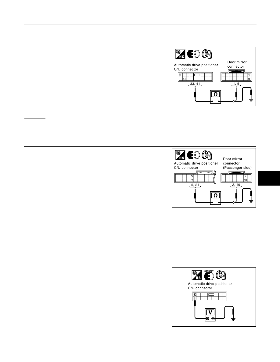
Check continuity between automatic drive positioner control unit
connector M50 terminal 33, 41 and door mirror (passenger side)
connector D32 terminal 1, 9.
3.
Check continuity between automatic drive positioner control unit
connector M50 terminals 33, 41 and ground.
OK or NG
OK
>> GO TO 3.
NG
>> Repair or replace harness between automatic drive positioner control unit and door mirror (pas-
senger side).
4.
CHECK HARNESS CONTINUITY 2
1.
Check continuity between automatic drive positioner control unit
connector M49 terminal 5, 21 and door mirror (passenger side)
connector D32 terminal 2, 10.
2.
Check continuity between automatic drive positioner control unit
connector M49 terminal 5, 21 and ground.
OK or NG
OK
>> Check the condition of the harness and connector.
NG
>> Repair or replace harness between automatic drive positioner control unit and door mirror (pas-
senger side).
Check Steering and Door Mirror Sensor Power Supply and Ground Circuit
INFOID:0000000001328127
1.
CHECK STEERING AND DOOR MIRROR SENSOR POWER SUPPLY
1.
Turn ignition switch OFF.
2.
Check voltage between automatic drive positioner control unit
connector M50 terminal 33 and ground.
OK or NG
OK
>> GO TO 2.
NG
>> Replace automatic drive positioner control unit.
2.
CHECK STEERING AND DOOR MIRROR SENSOR GROUND CIRCUIT
33 (G/W) – 1 (BR)
: Continuity should exist.
41 (B/Y) – 9 (G)
: Continuity should exist.
33 (G/W) – Ground
: Continuity should not exist.
41 (B/Y) – Ground
: Continuity should not exist.
PIIB8586E
5 (OR) – 2 (LG)
: Continuity should exist.
21 (G/Y) – 10 (P)
: Continuity should exist.
5 (OR) – Ground
: Continuity should not exist.
21 (G/Y) – Ground
: Continuity should not exist.
PIIB8587E
33 (G/W) – Ground
: Approx. 5V
PIIA4778E
Нет комментариевНе стесняйтесь поделиться с нами вашим ценным мнением.
Текст