Infiniti FX35 / FX45. Manual — part 922
SE-46
< SERVICE INFORMATION >
AUTOMATIC DRIVE POSITIONER
2.
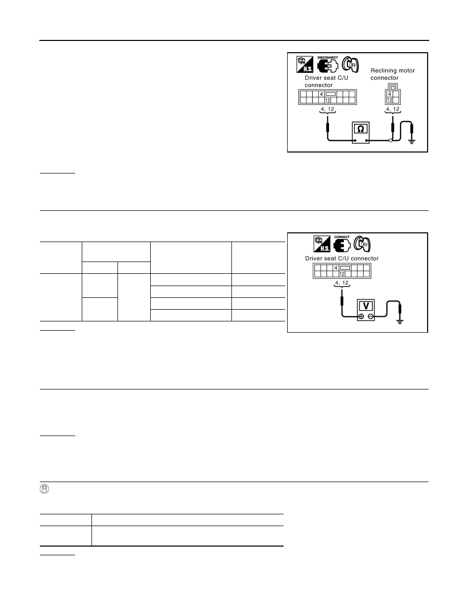
Disconnect driver seat control unit connector and reclining motor connector.
3.
Check continuity between driver seat control unit connector
B153 terminals 4, 12 and reclining motor connector B166 termi-
nals 4, 12.
4.
Check continuity between driver seat control unit connector
B153 terminals 4, 12 and ground.
OK or NG
OK
>> GO TO 4.
NG
>> Repair or replace harness between driver seat control unit and reclining motor.
4.
CHECK DRIVER SEAT CONTROL UNIT OUTPUT SIGNAL
1.
Connect the driver seat control unit.
2.
Reclining switch operate, check voltage between driver seat control unit connector and ground.
OK or NG
OK
>> Replace reclining motor.
NG
>> Replace driver seat control unit.
Check Front Lifting Motor Circuit
INFOID:0000000001328113
1.
CHECK FRONT LIFTING MECHANISM
Check the following.
• Operation malfunction caused by lifter mechanism deformation or pinched harness or other foreign materials
• Operation malfunction caused by foreign materials adhered to the lifter motor or lead screws
• Operation malfunction and interference with other parts by installation
OK or NG
OK
>> • GO TO 2 (With CONSULT-III).
• GO TO 3 (Without CONSULT-III).
NG
>> Repair the malfunctioning part and check again.
2.
CHECK FUNCTION
With CONSULT-III
Check operation with “SEAT LIFTER FR” in ACTIVE TEST.
OK or NG
OK
>> Front lifting motor circuit is OK.
NG
>> GO TO 3.
4 (G/L) – 4 (G/L)
: Continuity should exist.
12 (G/Y) – 12 (G/Y)
: Continuity should exist.
4 (G/L) – Ground
: Continuity should not exist.
12 (G/Y) – Ground
: Continuity should not exist.
PIIA6117E
Connector
Terminals
(Wire color)
Reclining switch condition
Voltage (V) (Ap-
prox.)
(+)
(–)
B153
4 (G/L)
Ground
FORWARD
Battery voltage
Other than above
0
12 (G/Y)
BACKWARD
Battery voltage
Other than above
0
PIIA6116E
Test item
Description
SEAT
LIFTER FR
The front end lifter motor is activated by receiving the drive signal.
AUTOMATIC DRIVE POSITIONER
SE-47
< SERVICE INFORMATION >
C
D
E
F
G
H
J
K
L
M
A
B
SE
N
O
P
3.
CHECK FRONT LIFTING MOTOR HARNESS CONTINUITY
1.
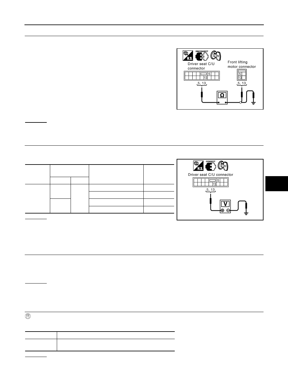
Turn ignition switch OFF.
2.
Disconnect driver seat control unit connector and front lifting motor connector.
3.
Check continuity between driver seat control unit connector
B153 and terminals 5, 13 and front lifting motor connector B164
terminals 5, 13.
4.
Check continuity between driver seat control unit connector
B153 and terminals 5, 13 and ground.
OK or NG
OK
>> GO TO 4.
NG
>> Repair or replace harness between driver seat control unit and front lifting motor.
4.
CHECK DRIVER SEAT CONTROL UNIT OUTPUT SIGNAL
1.
Connect the driver seat control unit connector.
2.
Front lifting switch operate, check voltage between driver seat control unit connector and ground.
OK or NG
OK
>> Replace front lifting motor.
NG
>> Replace driver seat control unit.
Check Rear Lifting Motor Circuit
INFOID:0000000001328114
1.
CHECK REAR LIFTING MECHANISM
Check the following.
• Operation malfunction caused by lifter mechanism deformation or pinched harness or other foreign materials
• Operation malfunction caused by foreign materials adhered to the lifter motor or lead screws
• Operation malfunction and interference with other parts by poor installation
OK or NG
OK
>> • GO TO 2 (With CONSULT-III).
• GO TO 3 (Without CONSULT-III).
NG
>> Repair the malfunctioning part and check again.
2.
CHECK FUNCTION
With CONSULT-III
Check operation with “SEAT LIFTER RR” in ACTIVE TEST.
OK or NG
5 (LG) – 5 (LG)
: Continuity should exist.
13 (Y) – 13 (Y)
: Continuity should exist.
5 (LG) – Ground
: Continuity should not exist.
13 (Y) – Ground
: Continuity should not exist.
PIIA6120E
Connector
Terminals
(Wire color)
Front lifting switch condition
Voltage (V)
(Approx.)
(+)
(–)
B153
5 (LG)
Ground
DOWN
Battery voltage
Other than above
0
13 (Y)
UP
Battery voltage
Other than above
0
PIIA6119E
Test item
Description
SEAT LIFTER
RR
The rear end lifter motor is activated by receiving the drive signal.
SE-48
< SERVICE INFORMATION >
AUTOMATIC DRIVE POSITIONER
OK
>> Rear lifting motor check is OK.
NG
>> GO TO 3.
3.
CHECK REAR LIFTING HARNESS CONTINUITY
1.
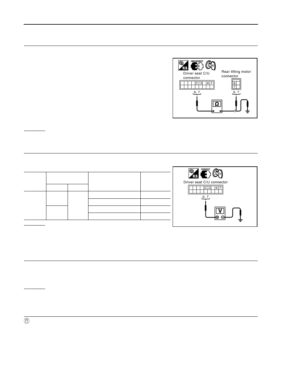
Turn ignition switch OFF.
2.
Disconnect driver seat control unit connector and rear lifting motor connector.
3.
Check continuity between driver seat control unit connector
B153 terminals 6, 7 and rear lifting motor connector B162 termi-
nals 6, 7.
4.
Check continuity between driver seat control unit connector
B153 terminals 6, 7 and ground.
OK or NG
OK
>> GO TO 4.
NG
>> Repair or replace harness between driver seat control unit and rear lifting motor.
4.
CHECK DRIVER SEAT CONTROL UNIT OUTPUT SIGNAL
1.
Connect the driver seat control unit connector.
2.
Rear lifting switch operate, check voltage between driver seat control unit connector and ground.
OK or NG
OK
>> Replace rear lifting motor.
NG
>> Replace driver seat control unit.
Check Telescopic Motor Circuit
INFOID:0000000001328115
1.
CHECK STEERING WHEEL TELESCOPIC MECHANISM
Check following.
• Operation malfunction caused by steering wheel telescopic mechanism deformation or pinched harness or
other foreign materials
• Operation malfunction and interference with other parts by poor installation
OK or NG
OK
>> • GO TO 2 (With CONSULT-III).
• GO TO 3 (Without CONSULT-III).
NG
>> Repair the malfunctioning part and check again.
2.
CHECK FUNCTION
With CONSULT-III
Check operation with “TELESCO MOTOR” in ACTIVE TEST.
6 (G/W) – 6 (G/W)
: Continuity should exist.
7 (G/B) – 7 (G/B)
: Continuity should exist.
6 (G/W) – Ground
: Continuity should not exist.
7 (G/B) – Ground
: Continuity should not exist.
PIIA6123E
Connector
Terminals
(Wire color)
Rear lifting switch condition
Voltage (V)
(Approx.)
(+)
(–)
B153
6 (G/W)
Ground
UP
Battery voltage
Other than above
0
7 (G/B)
DOWN
Battery voltage
Other than above
0
PIIA6122E
AUTOMATIC DRIVE POSITIONER
SE-49
< SERVICE INFORMATION >
C
D
E
F
G
H
J
K
L
M
A
B
SE
N
O
P
OK or NG
OK
>> Steering telescopic motor circuit is OK.
NG
>> GO TO 3.
3.
CHECK TELESCOPIC MOTOR HARNESS CONTINUITY
1.
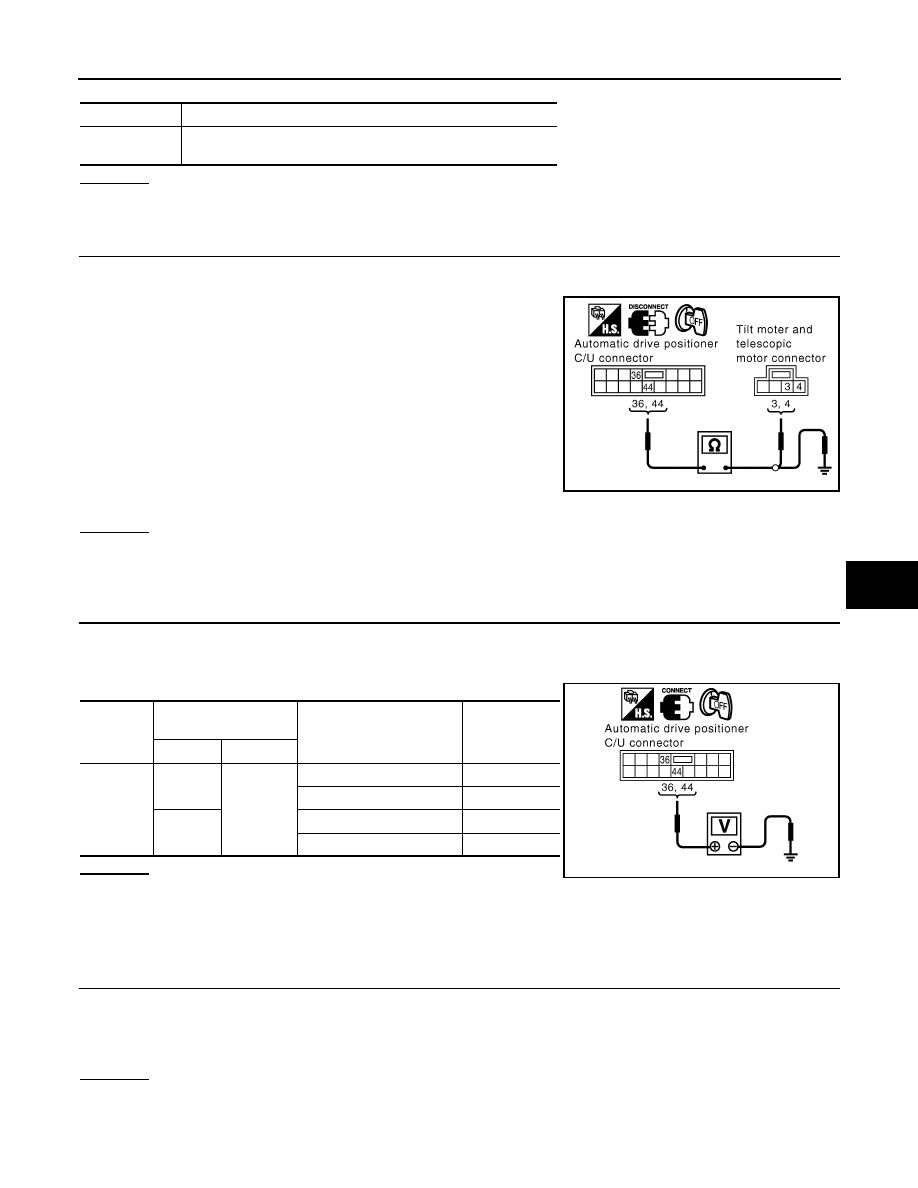
Turn ignition switch OFF.
2.
Disconnect automatic drive positioner control unit and tilt motor and telescopic motor connector.
3.
Check continuity between automatic drive positioner control unit
connector M50 terminals 36, 44 and tilt motor and telescopic
motor connector M27 terminals 3, 4.
4.
Check continuity between automatic drive positioner control unit
connector M50 terminals 36, 44 and ground.
OK or NG
OK
>> GO TO 4.
NG
>> Repair or replace harness between automatic drive positioner control unit and tilt motor and tele-
scopic motor.
4.
CHECK BCM OUTPUT SIGNAL
1.
Connect the automatic drive positioner control unit connector.
2.
Telescopic switch operate, check voltage between automatic drive positioner control unit connector and
ground.
OK or NG
OK
>> Replace tilt and telescopic motor.
NG
>> Replace automatic drive positioner control unit.
Check Tilt Motor Circuit
INFOID:0000000001328116
1.
CHECK STEERING WHEEL TILT MECHANISM
Check following.
• Operation malfunction caused by steering wheel tilt mechanism deformation or pinched harness and other
foreign materials
• Operation malfunction and interference with other parts by poor installation
OK or NG
OK
>> • GO TO 2 (With CONSULT-III).
• GO TO 3 (Without CONSULT-III).
NG
>> Repair the malfunctioning part.
Test item
Description
TELESCO
MOTOR
The telescopic motor is activated by receiving the drive signal.
36 (L/R) – 3 (L/R)
: Continuity should exist.
44 (L/W) – 4 (L/W)
: Continuity should exist.
36 (L/R) – Ground
:Continuity should not exist.
44 (L/W) – Ground
:Continuity should not exist.
PIIA5066E
Connector
Terminals
(Wire color)
Telescopic switch condition
Voltage (V)
(Approx.)
(+)
(–)
M50
36 (L/R)
Ground
FORWARD
Battery voltage
Other than above
0
44 (L/W)
BACKWARD
Battery voltage
Other than above
0
PIIA5068E
Нет комментариевНе стесняйтесь поделиться с нами вашим ценным мнением.
Текст