Infiniti FX35 / FX45. Manual — part 910
SC-28
< SERVICE INFORMATION >
CHARGING SYSTEM
• Make sure that alternator pulley nut is tight.
INSTALLATION
Installation is the reverse order of removal.
• Install alternator, and check tension of belt. Refer to
CAUTION:
Be sure to tighten “B” terminal nut carefully.
Disassembly and Assembly
INFOID:0000000001328259
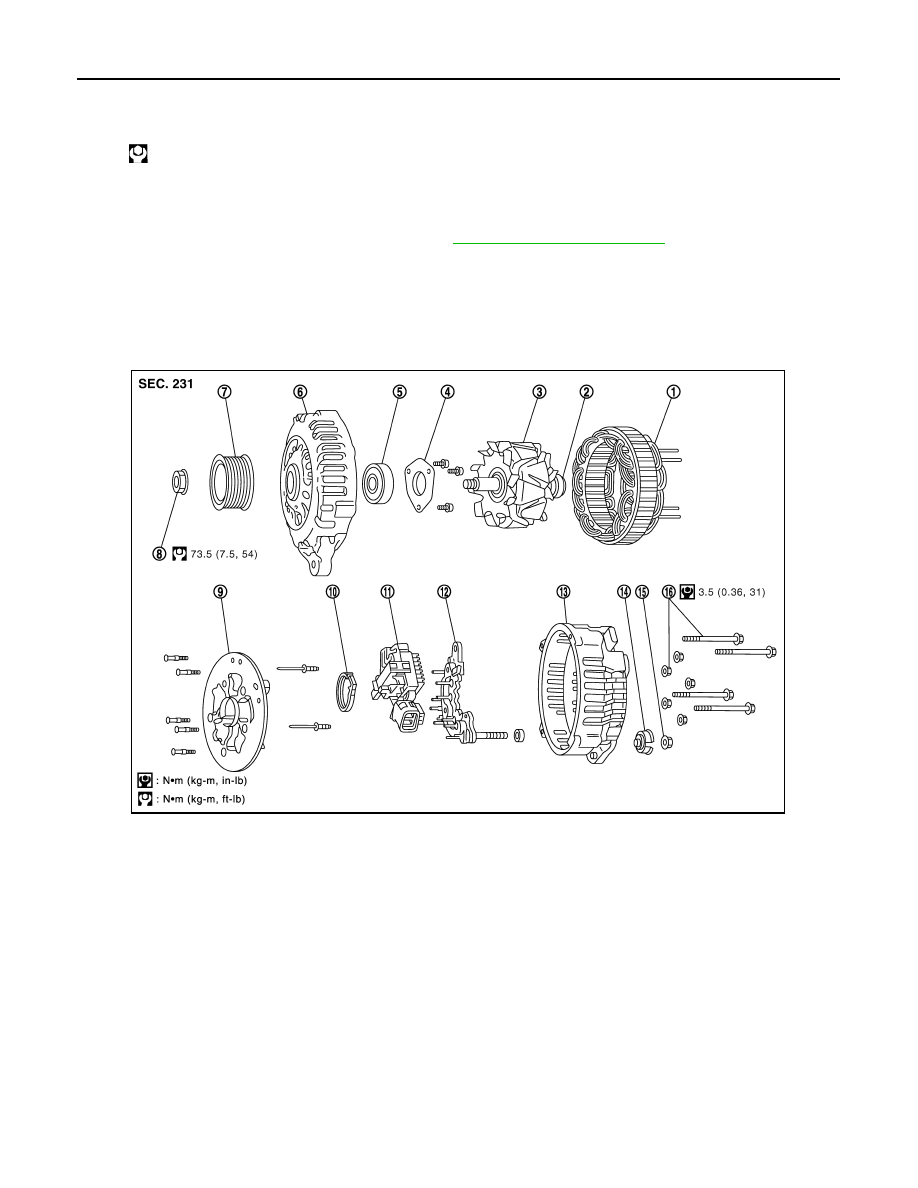
VK45DE ENGINE MODELS (LR1110-716B)
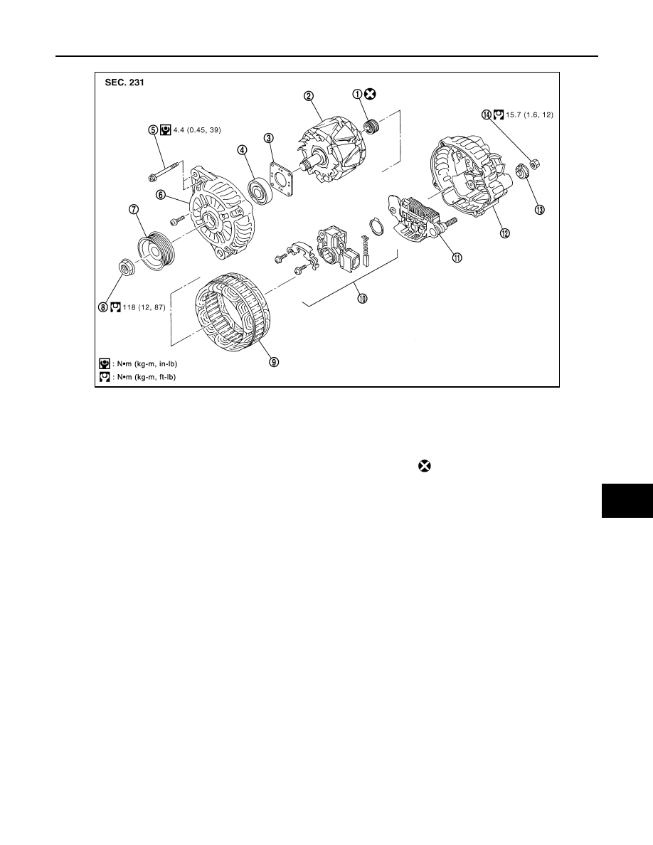
VQ35DE ENGINE MODELS (A3TG0191)
Alternator pulley nut:
: 118 N·m (12.0 kg-m, 87 ft-lb)
1.
Stator assembly
2.
Slip ring
3.
Rotor assembly
4.
Retainer
5.
Front bearing
6.
Front bracket assembly
7.
Pulley
8.
Pulley nut
9.
Fun guide
10.
Double labyrinth seal
11.
IC voltage regulator assembly
12. Diode assembly
13.
Rear bracket assembly
14. Bush
15. B terminal nut
16.
Through-bolt and nut
PKID0691E
CHARGING SYSTEM
SC-29
< SERVICE INFORMATION >
C
D
E
F
G
H
I
J
L
M
A
B
SC
N
O
P
1.
Rear bearing
2.
Rotor assembly
3.
Retainer
4.
Front bearing
5.
Through-bolt
6.
Front bracket assembly
7.
Pulley
8.
Pulley nut
9.
Stator assembly
10. IC voltage regulator assembly
11.
Diode assembly
12. Rear bracket assembly
13. Bush
14. B terminal nut
: Always replace after every disas-
sembly
PKID0692E
SC-30
< SERVICE INFORMATION >
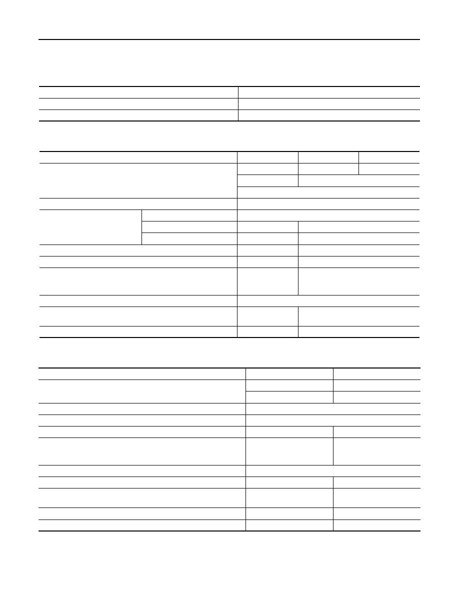
SERVICE DATA AND SPECIFICATIONS (SDS)
SERVICE DATA AND SPECIFICATIONS (SDS)
Battery
INFOID:0000000001328260
Starter
INFOID:0000000001328261
Alternator
INFOID:0000000001328262
Type
110D26L
Capacity
V - AH
12 - 75
Cold cranking current (For reference value)
A
720
Applied model
VK45DE
VQ35DE (2WD)
VQ35DE (AWD)
Type
M002T85075
S114-880A
S114-881A
MITSUBISHI make
HITACHI make
Reduction gear type
System voltage
V
12
No-load
Terminal voltage
V
11
Current
A
Less than 145
Less than 90
Revolution
rpm
More than 3,300
More than 2,880
Minimum diameter of commutator
mm (in)
31.4 (1.236)
28.0 (1.102)
Minimum length of brush
mm (in)
11.0 (0.433)
10.5 (0.413)
Brush spring tension
N (kg, lb)
26.7 - 36.1
(2.72 - 3.68,
6.80 - 8.12)
16.2 (1.65, 3.6)
Clearance between bearing metal and armature shaft
mm (in)
Less than 0.2 (0.008)
Clearance between pinion front edge and pinion stopper
mm (in)
0.5 - 2.0
(0.020 - 0.079)
—
Movement in height of pinion assembly
mm (in)
—
0.3 - 2.5 (0.012 - 0.098)
Applied model
VK45DE
VQ35DE
Type
LR1110 - 716B
A3TG0191
HITACHI make
MITSUBISHI make
Nominal rating
V - A
12 - 110
Ground polarity
Negative
Minimum revolution under no-load (When 13.5 V is applied)
rpm
Less than 1,100
Less than 1,000
Hot output current (When 13.5 V is applied)
A/rpm
More than 70/1,800
More than 91/2,500
More than 110/5,000
More than 37/1,300
More than 92/2,500
More than 103/5,000
Regulated output voltage
V
14.1 - 14.7
Minimum length of brush
mm (in)
More than 6.00 (0.236)
More than 5.00 (0.197)
Brush spring pressure
N (g, oz)
1.00 - 3.43
(102 - 350, 3.60 - 12.34)
4.8 - 6.0
(490 - 612, 17.28 - 21.60)
Slip ring minimum outer diameter
mm (in)
More than 26.0 (1.024)
More than 22.1 (0.870)
Rotor (Field coil) resistance
Ω
2.31
1.7 - 2.1
SE-1
BODY
C
D
E
F
G
H
J
K
L
M
SECTION
SE
A
B
SE
N
O
P
CONTENTS
SEAT
SERVICE INFORMATION . . . . . . .
DTC INDEX . . . . . . . . . . . . . . ..
U1000 . . . . . . . . . . . . . . . . . ....
B2112-B2128 . . . . . . . . . . . . . . ....
PRECAUTIONS . . . . . . . . . . . . ...
Service Notice . . . . . . . . . . . . . . ...
PREPARATION . . . . . . . . . . . . ...
Special Service Tool . . . . . . . . . . . .....
Commercial Service Tool . . . . . . . . . . ..
SQUEAK AND RATTLE TROUBLE DIAG-
NOSES . . . . . . . . . . . . . . . .
Work Flow . . . . . . . . . . . . . . . .....
Generic Squeak and Rattle Troubleshooting . . ....
Diagnostic Worksheet . . . . . . . . . . . .
AUTOMATIC DRIVE POSITIONER . . . . ...
System Description . . . . . . . . . . . . .
Component Parts and Harness Connector Loca-
tion . . . . . . . . . . . . . . . . . . ..
CAN Communication System Description . . . ...
CAN Communication Unit . . . . . . . . . ...
Schematic . . . . . . . . . . . . . . . ...
Wiring Diagram - AUT/DP - . . . . . . . . . .
Terminal and Reference Value for BCM . . . . .
Terminal and Reference Value for Automatic
Drive Positioner Control Unit . . . . . . . . ...
Terminal and Reference Value for Driver Seat
Control Unit . . . . . . . . . . . . . . . .
Work Flow . . . . . . . . . . . . . . . ...
Preliminary Check . . . . . . . . . . . . ...
CONSULT-III Function (AUTO DRIVE POS.) . . .
Check CAN Communication System . . . . . ..
Symptom Chart . . . . . . . . . . . . . ...
Check Sliding Motor Circuit . . . . . . . . . .
Check Reclining Motor Circuit . . . . . . . . .
Check Front Lifting Motor Circuit . . . . . . . .
Check Rear Lifting Motor Circuit . . . . . . . ..
Check Telescopic Motor Circuit . . . . . . . ...
Check Tilt Motor Circuit . . . . . . . . . . ...
Check Driver Side Mirror Motor Circuit . . . . .
Check Passenger Side Mirror Motor Circuit . . .
Check Sliding Sensor Circuit . . . . . . . . ...
Check Reclining Sensor Circuit . . . . . . . ...
Check Front Lifting Sensor Circuit . . . . . . ...
Check Rear Lifting Sensor Circuit . . . . . . ...
Check Telescopic Sensor Circuit . . . . . . . .
Check Tilt Sensor Circuit . . . . . . . . . . .
Check Driver Side Mirror Sensor Circuit . . . . ..
Check Passenger Side Mirror Sensor Circuit . . ..
Check Steering and Door Mirror Sensor Power
Supply and Ground Circuit . . . . . . . . . ..
Check Front Door Switch (Driver Side) Circuit . .
Check Sliding Switch Circuit . . . . . . . . .
Check Reclining Switch Circuit . . . . . . . .
Check Front Lifting Switch Circuit . . . . . . .
Check Rear Lifting Switch Circuit . . . . . . .
Check Power Seat Switch Ground Circuit . . . ...
Check Telescopic Switch Circuit . . . . . . . .
Check Tilt Switch Circuit . . . . . . . . . . ..
Check Door Mirror Remote Control Switch
(Changeover Switch) Circuit . . . . . . . . .
Check Door Mirror Remote Control Switch (Mirror
Switch) Circuit . . . . . . . . . . . . . . ..
Check A/T Device (Park Position Switch) Circuit .
Check Key Switch Circuit (With Intelligent Key) . ..
Check Key Switch Circuit (Without Intelligent Key) .
Check Seat Memory Switch Circuit . . . . . . .
Check Seat Memory Indicator Lamp Circuit . . .
Check UART Communication Line Circuit . . . ...
Check Lumbar Support Circuit . . . . . . . .
POWER SEAT . . . . . . . . . . . . ...
Wiring Diagram - SEAT - . . . . . . . . . . .
Нет комментариевНе стесняйтесь поделиться с нами вашим ценным мнением.
Текст