Infiniti FX35 / FX45. Manual — part 909
SC-24
< SERVICE INFORMATION >
CHARGING SYSTEM
Check “L” Terminal Circuit (Short)
1.
CHECK “L” TERMINAL CIRCUIT (SHORT)
1.
Turn ignition switch OFF.
2.
Disconnect alternator connector.
3.
Turn ignition switch ON.
Charge warning lamp should light up?
YES
>>
Check the following.
• Harness for short between combination meter and alternator
• Charge warning lamp (Combination meter)
NO
>> Go to
SC-21, "Trouble Diagnosis with Starting/Charging System Tester (Charging)"
DIAGNOSTIC PROCEDURE 3
Check “S” Terminal Circuit
1.
CHECK “S” TERMINAL CONNECTION
1.
Turn ignition switch OFF.
2.
Check if “S” terminal is clean and tight.
OK or NG
OK
>> GO TO 2.
NG
>> Repair “S” terminal connection. Confirm repair by performing complete Starting/Charging system
test. Refer to Technical Service Bulletin.
2.
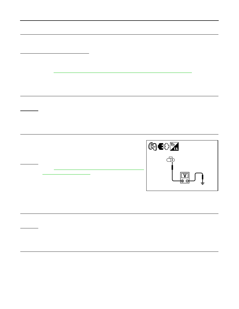
CHECK “S” TERMINAL CIRCUIT
1.
Disconnect alternator connector.
2.
Check voltage between alternator harness connector E311
(VK45DE) or F26 (VQ35DE) terminal 4 and ground.
OK or NG
OK
>> Go to
SC-21, "Trouble Diagnosis with Starting/Charging
NG
>> Harness for open between alternator and fuse.
DIAGNOSTIC PROCEDURE 4
Check “B” Terminal Circuit
1.
CHECK “B” TERMINAL CONNECTION
1.
Turn ignition switch OFF.
2.
Check if “B” terminal is clean and tight.
OK or NG
OK
>> GO TO 2.
NG
>> Repair “B” terminal connection. Confirm repair by performing complete Starting/Charging system
test. Refer to Technical Service Bulletin.
2.
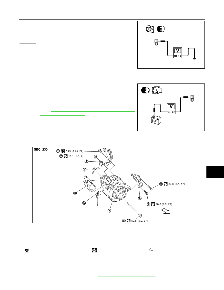
CHECK “B” TERMINAL CIRCUIT
4 – Ground
: Battery voltage
SKIB8494E
CHARGING SYSTEM
SC-25
< SERVICE INFORMATION >
C
D
E
F
G
H
I
J
L
M
A
B
SC
N
O
P
Check voltage between alternator “B” terminal E307 terminal 1 and
ground.
OK or NG
OK
>> GO TO 3.
NG
>>
Check the following.
• Harness for open between alternator and fusible link
(VK45DE and VQ35DE AWD)
• Harness for open between alternator and battery
(VQ35DE 2WD)
3.
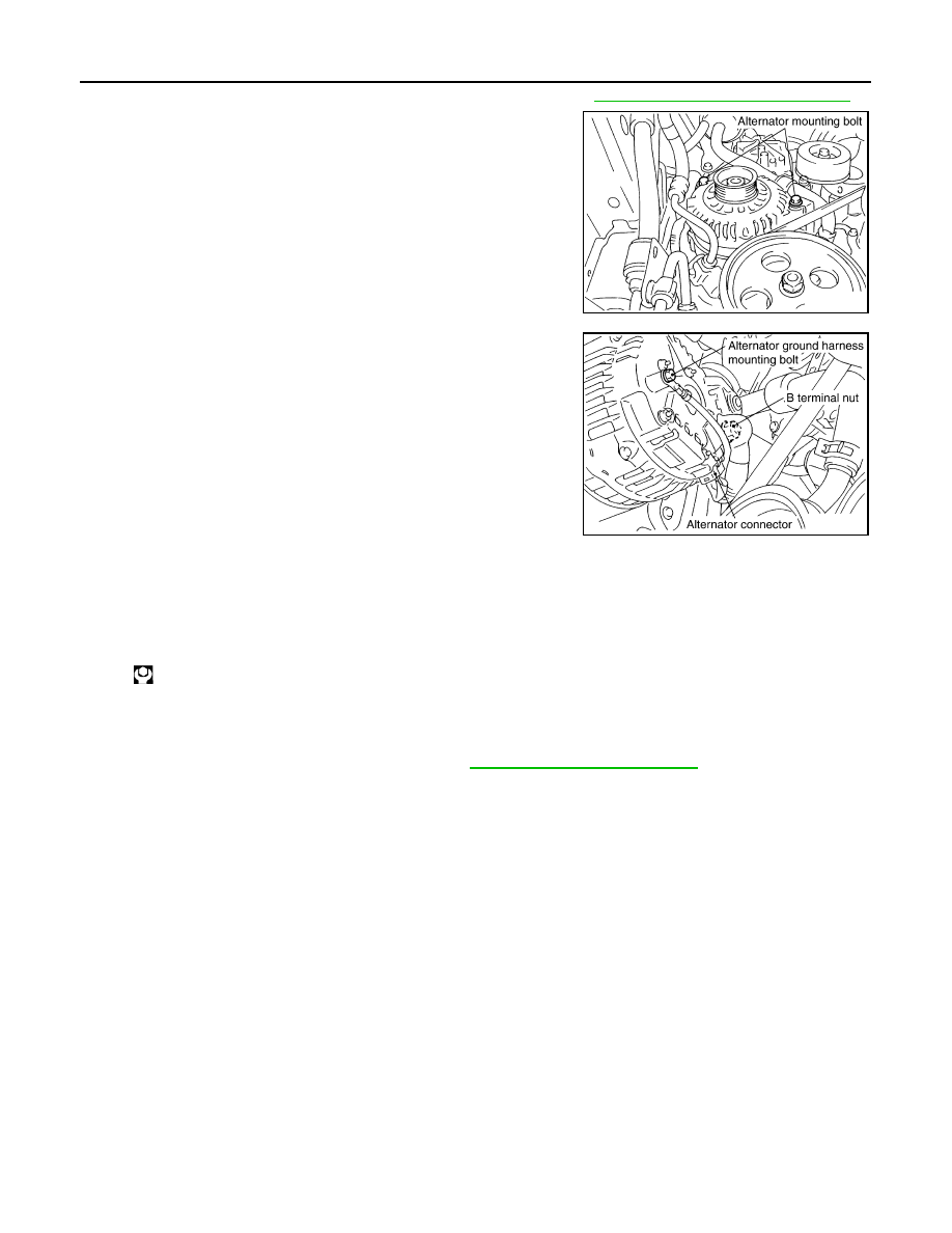
CHECK “B” TERMINAL CONNECTION (VOLTAGE DROP TEST)
1.
Start engine, then engine running at idle and warm.
2.
Check voltage between alternator “B” terminal E307 terminal 1
and battery positive terminal.
OK or NG
OK
SC-21, "Trouble Diagnosis with Starting/Charging
NG
>> Check harness between battery and alternator for poor
continuity.
Removal and Installation (VK45DE Engine Models)
INFOID:0000000001328257
REMOVAL
1.
Disconnect the battery cable from the negative terminal.
2.
Remove engine front undercover, using power tools.
3.
Remove radiator shroud (lower). Refer to
CO-40, "Removal and Installation"
.
1 – Ground
: Battery voltage
PKIB8809E
1 – Battery positive terminal
: Less than 0.2 V
PKIB8810E
1.
Alternator ground harness mounting bolt
2.
B terminal nut
3.
B terminal harness
4.
Alternator Nut
5.
Alternator bracket
6.
Alternator connector
7.
Alternator
8.
Alternator mounting bolt
9.
Alternator stay
10. Alternator mounting bolt
11.
Alternator stay mounting bolt
12. Alternator ground harness
: N·m (kg-m, in-lb)
: N·m (kg-m, ft-lb)
: Engine front
SKIB7209E
SC-26
< SERVICE INFORMATION >
CHARGING SYSTEM
4.
Remove alternator, water pump and A/C compressor belt. Refer to
EM-170, "Removal and Installation"
5.
Remove alternator mounting bolts, using power tools.
6.
Disconnect alternator connector.
7.
Remove “B” terminal nut.
8.
Remove alternator ground harness mounting bolt.
9.
Remove alternator assembly downward from the vehicle.
ALTERNATOR PULLEY INSPECTION
Perform the following.
• Make sure that alternator pulley does not rattle.
• Make sure that alternator pulley nut is tight.
INSTALLATION
Installation is the reverse order of removal.
• Install alternator, and check tension of belt. Refer to
EM-170, "Checking Drive Belts"
.
CAUTION:
Be sure to tighten “B” terminal nut carefully.
PKIA2954E
PKIA2820E
Alternator pulley nut:
: 73.5 N·m (7.5 kg-m, 54 ft-lb)
CHARGING SYSTEM
SC-27
< SERVICE INFORMATION >
C
D
E
F
G
H
I
J
L
M
A
B
SC
N
O
P
Removal and Installation (VQ35DE Engine Models)
INFOID:0000000001328258
REMOVAL
1.
Disconnect the battery cable from the negative terminal.
2.
Remove engine front undercover, using power tools.
3.
Remove alternator and power steering oil pump belt. Refer to
EM-15, "Removal and Installation"
.
4.
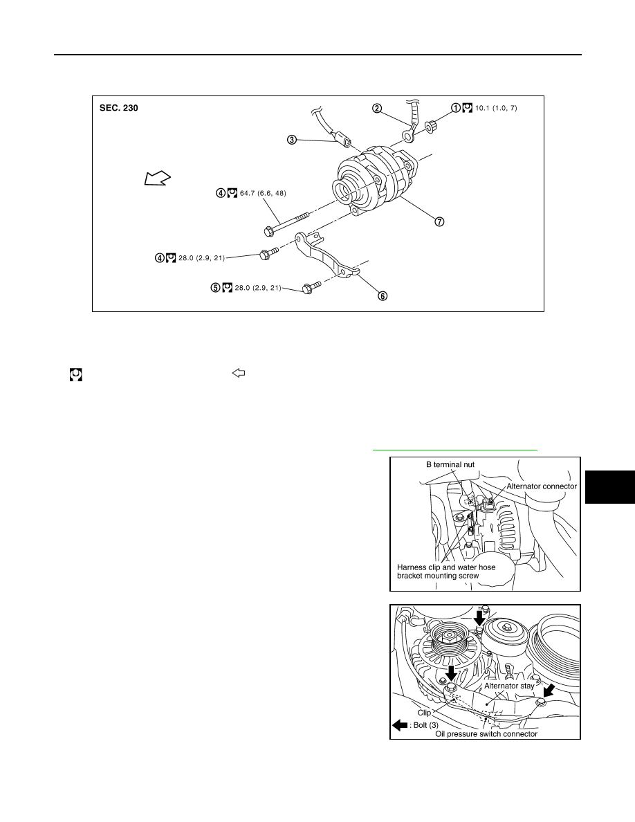
Disconnect alternator connector.
5.
Remove “B” terminal nut.
6.
Remove harness clip and water hose bracket from alternator.
7.
Remove oil pressure switch harness clip from alternator stay.
(2WD)
8.
Disconnect oil pressure switch connector. (2WD)
9.
Remove alternator stay mounting bolts and alternator stay, using
power tools.
10. Remove alternator mounting bolt, using power tools.
11. Remove alternator assembly downward from the vehicle.
ALTERNATOR PULLEY INSPECTION
Perform the following.
• Make sure that alternator pulley does not rattle.
1.
B terminal nut
2.
B terminal harness
3.
Alternator connector
4.
Alternator mounting bolt
5.
Alternator stay mounting bolt
6.
Alternator stay
7.
Alternator
: N·m (kg-m, ft-lb)
: Engine front
PKIB8815E
PKIA2358E
PKIA1923E
Нет комментариевНе стесняйтесь поделиться с нами вашим ценным мнением.
Текст