Infiniti FX35 / FX45. Manual — part 911
SE-2
Description . . . . . . . . . . . . . . . ..
Wiring Diagram - HSEAT - . . . . . . . . . .
FRONT SEAT . . . . . . . . . . . . .
Removal and Installation . . . . . . . . . . .
REAR SEAT . . . . . . . . . . . . . ..

DTC INDEX
SE-3
< SERVICE INFORMATION >
C
D
E
F
G
H
J
K
L
M
A
B
SE
N
O
P
SERVICE INFORMATION
DTC INDEX
U1000
INFOID:0000000001529390
B2112-B2128
INFOID:0000000001529391
CONSULT display
DTC detection condition
Reference page
U1000: CAN COMM CIRCUIT
When driver seat control unit is not transmitting or receiving
CAN communication signal for 2 seconds or more.
CONSULT display
DTC detection condition
Reference page
B2112: SEAT SLIDE
When any manual and automatic operations are not per-
formed, if any motor operations of seat slide is detected for
0.1 second or more, status is judged
“Output error”.
SE-44, "Check Sliding Mo-
tor Circuit"
SE-53, "Check Sliding Sen-
sor Circuit"
B2113: SEAT RECLINING
When any manual and automatic operations are not per-
formed, if any motor operations of seat reclining is detected
for 0.1 second or more, status is judged “Output error”.
SE-45, "Check Reclining
Motor Circuit"
SE-54, "Check Reclining
Sensor Circuit"
B2114: SEAT LIFTER FR
When any manual and automatic operations are not per-
formed, if any motor operations of seat lifting FR is detect-
ed for 0.1 second or more, status is judged “Output error”.
SE-46, "Check Front Lifting
Motor Circuit"
SE-55, "Check Front Lifting
Sensor Circuit"
B2115: SEAT LIFTER RR
When any manual and automatic operations are not per-
formed, if any motor operations of seat lifting RR is detect-
ed for 0.1 second or more, status is judged “Output error”.
SE-47, "Check Rear Lifting
Motor Circuit"
SE-56, "Check Rear Lifting
Sensor Circuit"
B2116: TILT OUTPUT
When any manual and automatic operations are not per-
formed, if any motor operations of steering tilt is detected
for 0.1 second or more, status is judged “Output error”.
SE-49, "Check Tilt Motor
Circuit"
SE-58, "Check Tilt Sensor
Circuit"
B2118: TILT SENSOR
When driver seat control unit detects 0.1V or lower, or 4.9V
or higher, from tilt sensor for 0.5 seconds or more.
SE-58, "Check Tilt Sensor
Circuit"
B2119: TELESCO SENSOR
When driver seat control unit detects 0.1V or lower, or 4.9V
or higher, from
telescopic sensor for 0.5 seconds or more.
SE-57, "Check Telescopic
Sensor Circuit"
B2125: P RANGE SW
With the A/T selector lever in P position (P range switch
ON), if the vehicle speed of 7 km/h (4 MPH) or higher was
input the detention switch input system is judged malfunc-
tioning.
SE-74, "Check A/T Device
(Park Position Switch) Cir-
cuit"
B2128: UART COMM
Malfunction is detected in UART communication.
SE-4
< SERVICE INFORMATION >
PRECAUTIONS
PRECAUTIONS
Precaution for Supplemental Restraint System (SRS) "AIR BAG" and "SEAT BELT
PRE-TENSIONER"
INFOID:0000000001612906
The Supplemental Restraint System such as “AIR BAG” and “SEAT BELT PRE-TENSIONER”, used along
with a front seat belt, helps to reduce the risk or severity of injury to the driver and front passenger for certain
types of collision. This system includes seat belt switch inputs and dual stage front air bag modules. The SRS
system uses the seat belt switches to determine the front air bag deployment, and may only deploy one front
air bag, depending on the severity of a collision and whether the front occupants are belted or unbelted.
Information necessary to service the system safely is included in the “SUPPLEMENTAL RESTRAINT SYS-
TEM” and “SEAT BELTS” of this Service Manual.
WARNING:
• To avoid rendering the SRS inoperative, which could increase the risk of personal injury or death in
the event of a collision which would result in air bag inflation, all maintenance must be performed by
an authorized NISSAN/INFINITI dealer.
• Improper maintenance, including incorrect removal and installation of the SRS, can lead to personal
injury caused by unintentional activation of the system. For removal of Spiral Cable and Air Bag
Module, see the “SUPPLEMENTAL RESTRAINT SYSTEM”.
• Do not use electrical test equipment on any circuit related to the SRS unless instructed to in this
Service Manual. SRS wiring harnesses can be identified by yellow and/or orange harnesses or har-
ness connectors.
Service Notice
INFOID:0000000001328091
• When removing or installing various parts, place a cloth or padding onto the vehicle body to prevent
scratches.
• Handle trim, molding, instruments, grille, etc. carefully during removing or installing. Be careful not to oil or
damage them.
• Apply sealing compound where necessary when installing parts.
• When applying sealing compound, be careful that the sealing compound does not protrude from parts.
• When replacing any metal parts (for example body outer panel, members, etc.), be sure to take rust preven-
tion measures.
PREPARATION
SE-5
< SERVICE INFORMATION >
C
D
E
F
G
H
J
K
L
M
A
B
SE
N
O
P
PREPARATION
Special Service Tool
INFOID:0000000001328092
The actual shapes of Kent-Moore tools may differ from those of special service tools illustrated here.
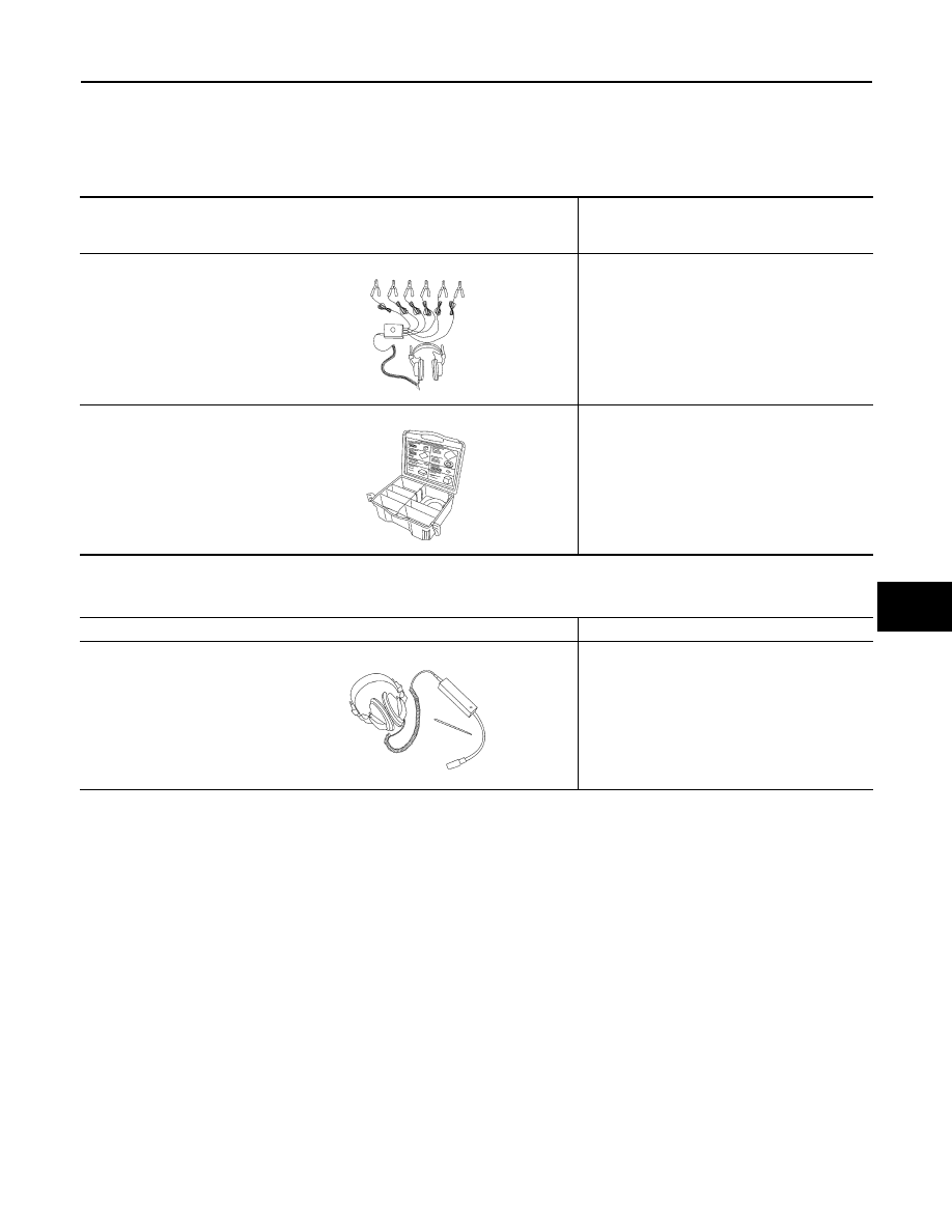
Commercial Service Tool
INFOID:0000000001328093
Tool number
(Kent-Moore No.)
Tool name
Description
(J39570)
Chassis ear
Location the noise
(J43980)
NISSAN Squeak and Rattle
Kit
Repairing the cause of the noise
SIIA0993E
SIIA0994E
Tool name
Description
Engine ear
Location the noise
SIIA0995E
Нет комментариевНе стесняйтесь поделиться с нами вашим ценным мнением.
Текст