Infiniti FX35 / FX45. Manual — part 977

WW-30
< SERVICE INFORMATION >
REAR WIPER AND WASHER SYSTEM
REAR WIPER AND WASHER SYSTEM
Component Parts and Harness Connector Location
INFOID:0000000001328576
System Description
INFOID:0000000001328577
• Wiper switch (combination switch) is composed of a combination of 5 output terminals and 5 input terminals.
Terminal combination status is read by BCM (body control module) when switch is turned ON.
• BCM controls rear wiper ON and INT (intermittent) operation.
Power supplied at all times
• through 50 A fusible link (letter M, located in fuse, fusible link and relay box)
• to BCM terminal 55,
• through 15 A fuse [No. 22, located in fuse block (J/B)]
• to BCM terminal 42.
When ignition switch ON or START position, power is supplied
• through 15 A fuse [No.1, located in fuse block (J/B)]
• to BCM terminal 38,
• through 10 A fuse [No. 84, located in IPDM E/R (intelligent power distribution module engine room)]
• to combination switch terminal 14.
Ground is supplied
• to BCM terminals 49 and 52
• through grounds M35, M45 and M85,
• to combination switch terminal 12
• through grounds M35, M45 and M85.
REAR WIPER OPERATION
When the wiper switch is in rear wiper ON position, BCM detects rear wiper ON signal by BCM wiper switch
reading function.
BCM operates rear wiper motor, power is supplied
• through BCM terminal 70
• to rear wiper motor 4.
Ground is supplied
• to rear wiper motor terminal 2
• through grounds B15 and B45.
With power and ground supplied, the rear wiper operates.
PKIC9708E
REAR WIPER AND WASHER SYSTEM
WW-31
< SERVICE INFORMATION >
C
D
E
F
G
H
I
J
L
M
A
B
WW
N
O
P
INTERMITTENT OPERATION
The rear wiper motor operates the wiper arms at low speed approximately every 7 seconds.
When the wiper switch is in rear wiper INT position, BCM detects rear wiper INT signal by BCM wiper switch
reading function (Refer to
).
BCM operates rear wiper motor, power supplied
• through BCM terminal 70
• to rear wiper motor terminal 4.
Ground is supplied
• to rear wiper motor terminal 2
• through grounds B15 and B45.
With power and ground supplied, rear wiper operates at intermittent.
AUTO STOP OPERATION
With rear wiper switch turned OFF, rear wiper motor will continue to operate until wiper arm reaches rear wiper
stopper.
Then wiper motor turns the other way and wiper arm moves once until wiper arm reaches stopper.
WASHER OPERATION
When the wiper switch is in rear wiper washer position, BCM detects rear wiper washer signal by BCM wiper
switch reading function (Refer to
), and combination switch (wiper switch) ground
is supplied
• to combination switch terminal 11
• through front and rear washer pump terminal 2,
• to front and rear washer pump terminal 1
• through combination switch terminal 13
• through combination switch terminal 12
• through grounds M35, M45 and M85.
With ground supplied, front and rear washer pump is operated.
When the BCM detects that washer pump has operated for. 0.4 seconds or linger, BCM operates rear wiper
pump low speed.
When the BCM detects washer switch is OFF, low speed operation cycles approximately 3 times and then
stops.
BCM WIPER SWITCH READING FUNCTION
WW-32
< SERVICE INFORMATION >
REAR WIPER AND WASHER SYSTEM
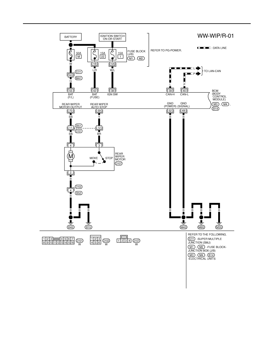
Wiring Diagram - WIP/ R -
INFOID:0000000001328578
TKWM4376E

REAR WIPER AND WASHER SYSTEM
WW-33
< SERVICE INFORMATION >
C
D
E
F
G
H
I
J
L
M
A
B
WW
N
O
P
Terminal and Reference Value for BCM
INFOID:0000000001328579
CAUTION:
• Check combination switch system terminal waveform under the loaded condition with lighting
switch, turn signal switch and wiper switch OFF not to be fluctuated by overloaded.
• Turn wiper intermittent dial position to 4 except when checking waveform or voltage of wiper inter-
mittent dial position. Wiper intermittent dial position can be confirmed on CONSULT-III. Refer to
15, "CONSULT-III Functions (BCM)"
.
TKWM4377E
Нет комментариевНе стесняйтесь поделиться с нами вашим ценным мнением.
Текст