Infiniti FX35 / FX45. Manual — part 221
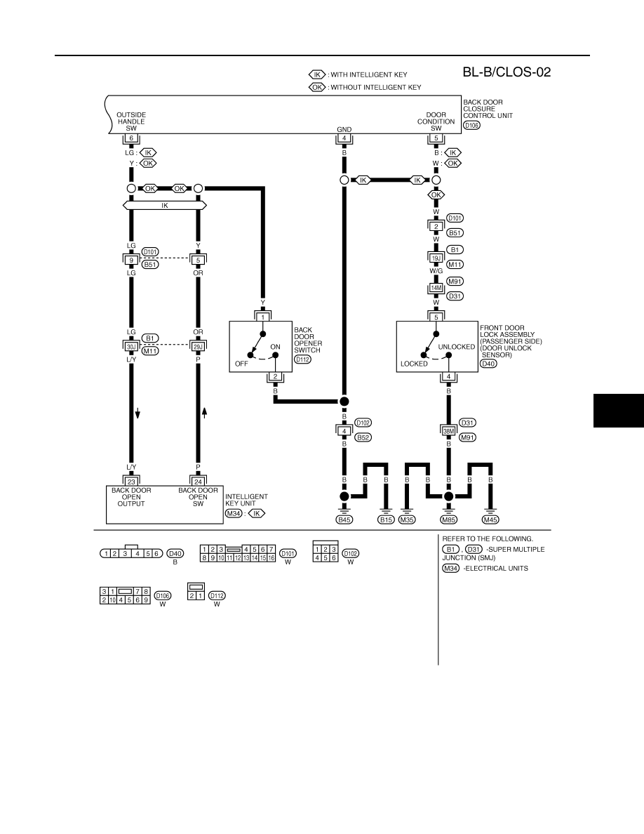
BACK DOOR AUTO CLOSURE SYSTEM
BL-151
< SERVICE INFORMATION >
C
D
E
F
G
H
J
K
L
M
A
B
BL
N
O
P
TIWM1672E
BL-152
< SERVICE INFORMATION >
BACK DOOR AUTO CLOSURE SYSTEM
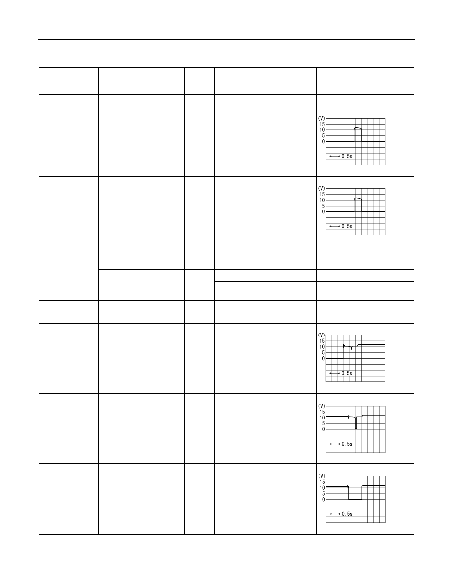
Terminal and Reference Value for Back Door Closure Control Unit
INFOID:0000000001327891
*, (): Models with Intelligent Key
Termi-
nal
Wire
color
Item
Signal
Input/
output
Condition
Voltage (V)
(Approx.)
1
R
Power source (Fuse)
Input
—
Battery voltage
2
PU
Closure motor (open) signal
Output
Fully close
→
fully open
3
G
Closure motor (close) signal
Output
Fully open
→
fully close
4
B
Ground
—
—
0
5
W
(B)
Ground*
—
—
0*
Unlock sensor signal
(passenger side)
Input
Passenger side door lock is locked
5
Passenger side door lock is un-
locked
0
6
Y
(LG)
Back door opener switch sig-
nal
Input
Back door opener switch is ON
0
Other than above
5
7
OR
Half-latch switch signal
Input
Fully open
→
fully close
8
L
Close switch signal
Input
Fully open
→
fully close
9
P
Open switch signal
Input
Fully open
→
fully close
SIIA1480J
SIIA1480J
SIIA1479J
SIIA1478J
SIIA1481J
BACK DOOR AUTO CLOSURE SYSTEM
BL-153
< SERVICE INFORMATION >
C
D
E
F
G
H
J
K
L
M
A
B
BL
N
O
P
Work Flow
INFOID:0000000001327892
1.
Check the symptom and customer's requests.
2.
Understand the outline of system. Refer to
3.
Perform the preliminary check, Refer to
4.
According to the trouble diagnosis chart, repair or replace the cause of the malfunction. Refer to
"Trouble Diagnosis Chart by Symptom"
.
5.
Does back door auto closure system operate normally? If Yes, GO TO 6, If No, GO TO 4.
6.
INSPECTION END
Preliminary Check
INFOID:0000000001327893
Remove the fuse No.18 for the back door closure with the back door closure inactive.
Check that the back door can be open / close normally.
CAUTION:
It is judged it is abnormal, discontinues closure operation, and drive lever returns to a neutral position
if not becoming full-latch within about three seconds after half-latch.
When this operation is done continuously three times, both back door closure and back door opener
switch are not operated because the function of back door closure is stopped.
Thing to reset power supply by pulling out and opening fuse in that case.
Trouble Diagnosis Chart by Symptom
INFOID:0000000001327894
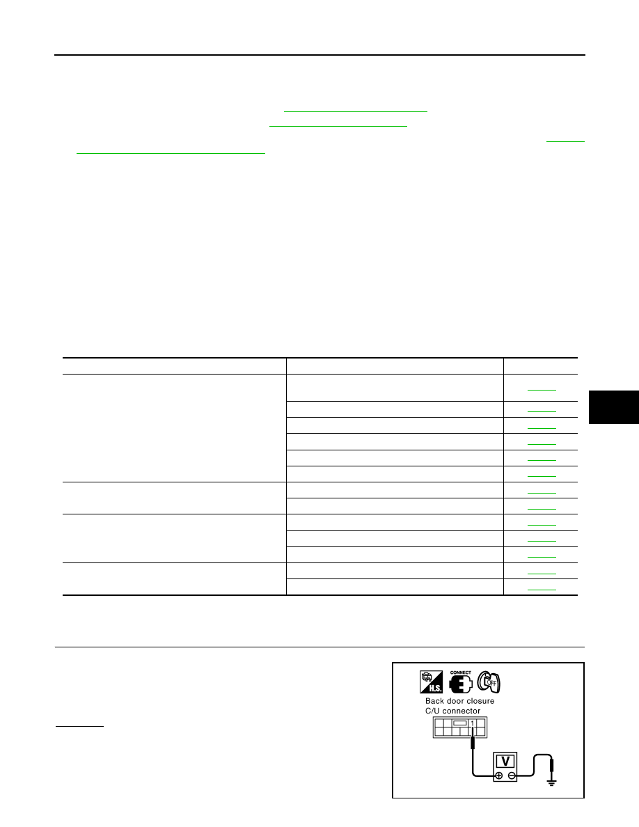
Check Back Door Closure Control Unit Power Supply and Ground Circuit
INFOID:0000000001327895
1.
CHECK POWER SUPPLY CIRCUIT
1.
Turn ignition switch OFF.
2.
Check voltage between back door closure control unit connector
D106 terminal 1 and ground.
OK or NG
OK
>> GO TO 2.
NG
>>
Check the following.
• 15A fuse [No.18, located in fuse block (J/B)]
• Harness for open or short between back door closure
control unit and fuse.
Symptom
Diagnostic procedure and repair order
Refer to page
Back door closure does not operate.
1. Check back door closure motor power supply and
ground circuit
2. Check half-latch switch
3. Check close switch
4. Check open switch
5. Check closure motor
6. Replace back door closure control unit.
Back door does not open (with Intelligent Key system).
1. Check Intelligent Key system
2. Check back door opener switch
Back door does not open
1. Check back door opener switch
2. Check unlock sensor
3. Replace back door closure control unit.
Back door does not enter fully closed states through
back door closure operates.
1. Back door fitting adjustment.
2. Replace back door lock assembly.
1 (R) – Ground
: Battery voltage
PIIA6166E
BL-154
< SERVICE INFORMATION >
BACK DOOR AUTO CLOSURE SYSTEM
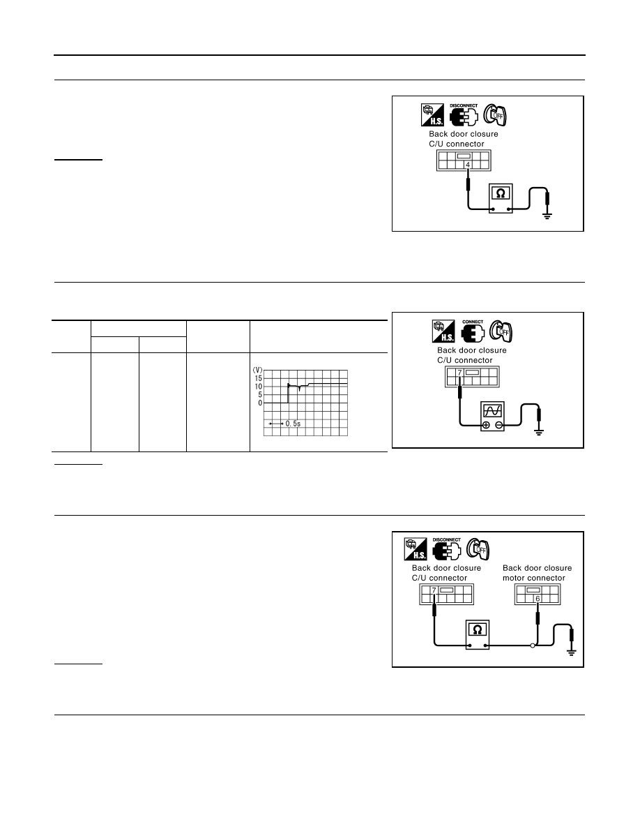
2.
CHECK GROUND CIRCUIT
1.
Disconnect back door closure control unit connector.
2.
Check continuity between back door closure control unit con-
nector D106 terminal 4 and ground.
OK or NG
OK
>> Power supply and ground circuit are OK.
NG
>> Repair or replace harness.
Check Half-Latch Switch
INFOID:0000000001327896
1.
CHECK HALF-LATCH SWITCH SIGNAL
1.
Turn ignition switch OFF.
2.
Check the signal between back door closure control unit connector and ground with oscilloscope.
OK or NG
OK
>> Half-latch switch is OK.
NG
>> GO TO 2.
2.
CHECK HARNESS CONTINUITY
1.
Disconnect back door closure control unit and back door closure motor connector.
2.
Check continuity between back door closure control unit con-
nector D106 terminal 7 and back door closure motor connector
D109 terminal 6.
3.
Check continuity between back door closure control unit con-
nector D106 terminal 7 and ground.
OK or NG
OK
>> GO TO 3.
NG
>> Repair or replace harness.
3.
CHECK GROUND CIRCUIT
4 (B) – Ground
: Continuity should exist.
PIIA6167E
Con-
nector
Terminals (Wire color)
Back door
condition
Signal
(Reference value)
(+)
(-)
D106
7 (OR)
Ground
Fully open
→
fully closed
PIIA6168E
SIIA1479J
7 (OR) – 6 (OR)
: Continuity should exist.
7 (OR) – Ground
: Continuity should not exist.
PIIA6169E
Нет комментариевНе стесняйтесь поделиться с нами вашим ценным мнением.
Текст