Infiniti FX35 / FX45. Manual — part 222
BACK DOOR AUTO CLOSURE SYSTEM
BL-155
< SERVICE INFORMATION >
C
D
E
F
G
H
J
K
L
M
A
B
BL
N
O
P
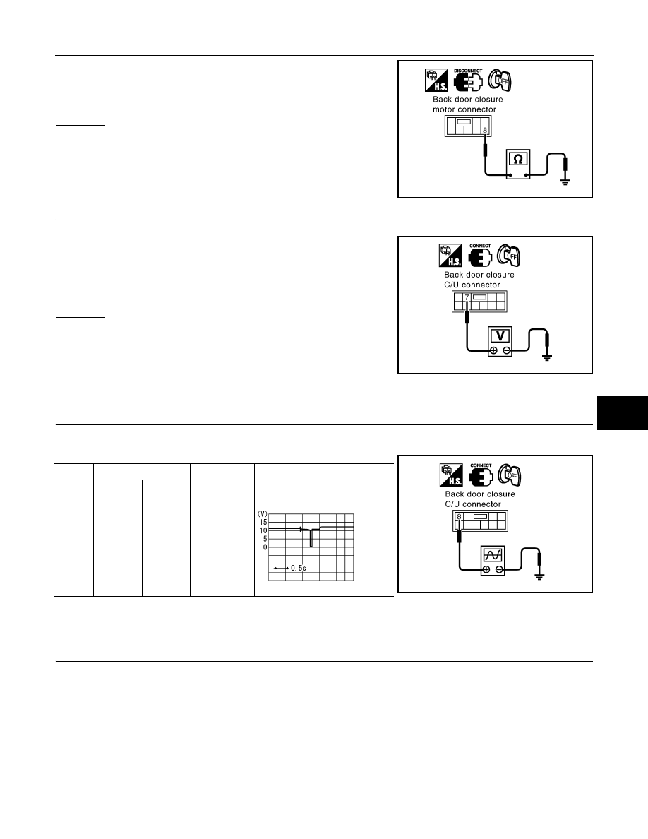
Check continuity between back door closure motor connector D109
terminal 8 and ground.
OK or NG
OK
>> GO TO 4.
NG
>> Repair or replace harness.
4.
CHECK BACK DOOR CLOSURE CONTROL UNIT OUTPUT SIGNAL
1.
Connect back door closure control unit connector.
2.
Check voltage between back door closure control unit connector
D106 terminal 7 and ground.
OK or NG
OK
>> Replace back door lock assembly.
NG
>> Replace back door closure control unit.
Check Close Switch
INFOID:0000000001327897
1.
CHECK CLOSE SWITCH SIGNAL
1.
Turn ignition switch OFF.
2.
Check the signal between back door closure control unit connector and ground with oscilloscope.
OK or NG
OK
>> Close switch is OK.
NG
>> GO TO 2.
2.
CHECK HARNESS CONTINUITY
1.
Disconnect back door closure control unit and back door closure motor connector.
8 (B) – Ground
: Continuity should exist.
PIIA6170E
Back door is closed
7 (OR) – Ground
: Battery voltage
PIIA6172E
Con-
nector
Terminals (Wire color)
Back door
condition
Signal
(Reference value)
(+)
(-)
D106
8 (L)
Ground
Fully open
→
fully closed
PIIA6171E
SIIA1478J
BL-156
< SERVICE INFORMATION >
BACK DOOR AUTO CLOSURE SYSTEM
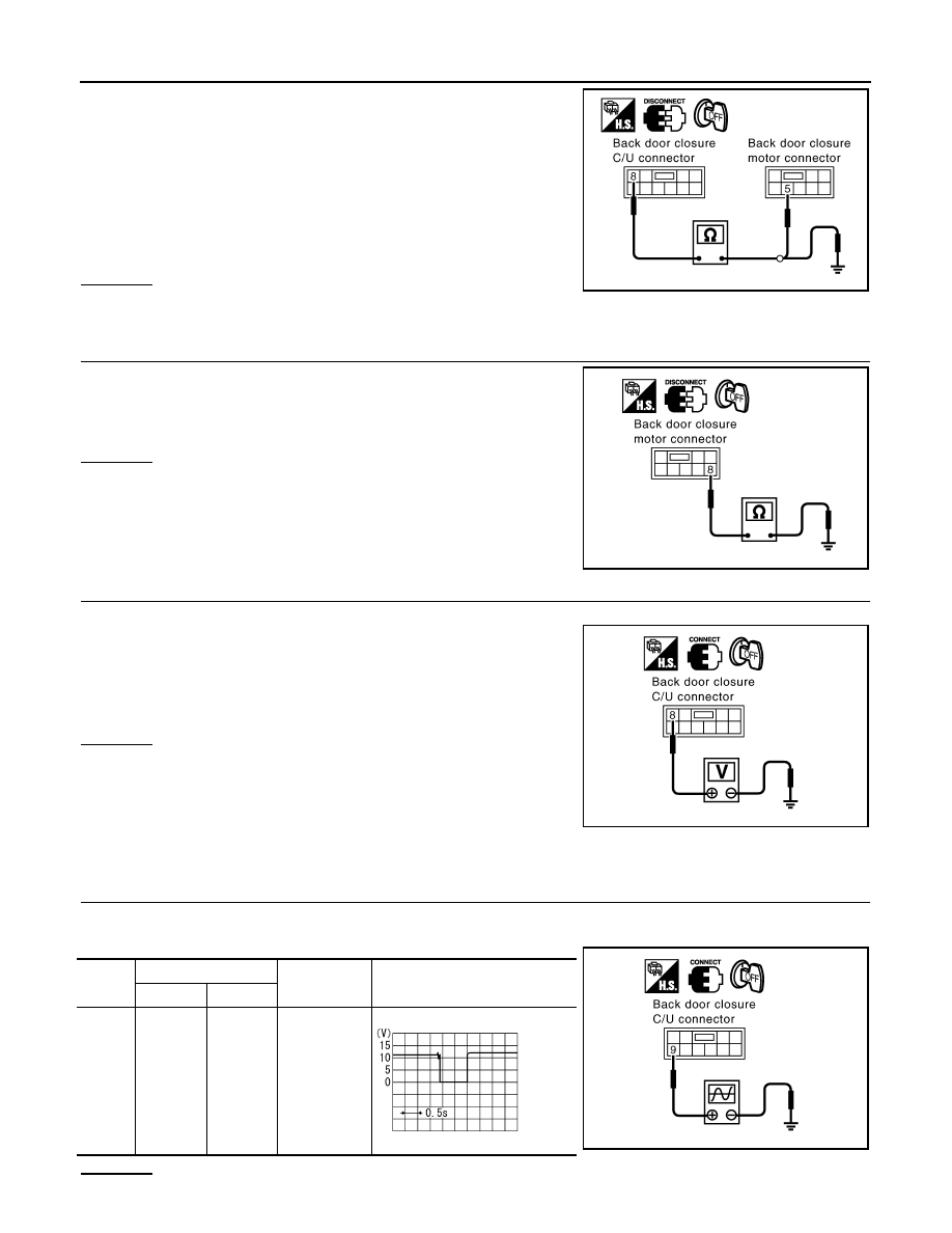
2.
Check continuity between back door closure control unit con-
nector D106 terminal 8 and back door closure motor connector
D109 terminal 5.
3.
Check continuity between back door closure control unit con-
nector D106 terminal 8 and ground.
OK or NG
OK
>> GO TO 3.
NG
>> Repair or replace harness.
3.
CHECK GROUND CIRCUIT
Check continuity between back door closure motor connector D109
terminal 8 and ground.
OK or NG
OK
>> GO TO 4.
NG
>> Repair or replace harness.
4.
CHECK BACK DOOR CLOSURE CONTROL UNIT OUTPUT SIGNAL
1.
Connect back door closure control unit connector.
2.
Check voltage between back door closure control unit connector
D106 terminal 8 and ground.
OK or NG
OK
>> Replace back door lock assembly.
NG
>> Replace back door closure control unit.
Check Open Switch
INFOID:0000000001327898
1.
CHECK OPEN SWITCH SIGNAL
1.
Turn ignition switch OFF.
2.
Check the signal between back door closure control unit connector and ground with oscilloscope.
OK or NG
8 (L) – 5 (L)
: Continuity should exist.
8 (L) – Ground
: Continuity should not exist.
PIIA6174E
8 (B) – Ground
: Continuity should exist.
PIIA6170E
Back door is closed
8 (L) – Ground
: Battery voltage
PIIA6173E
Con-
nector
Terminals (Wire color)
Back door
condition
Signal
(Reference value)
(+)
(-)
D106
9 (P)
Ground
Fully open
→
fully closed
PIIA6175E
SIIA1481J
BACK DOOR AUTO CLOSURE SYSTEM
BL-157
< SERVICE INFORMATION >
C
D
E
F
G
H
J
K
L
M
A
B
BL
N
O
P
OK
>> Open switch is OK.
NG
>> GO TO 2.
2.
CHECK HARNESS CONTINUITY
1.
Disconnect back door closure control unit and back door closure motor connector.
2.
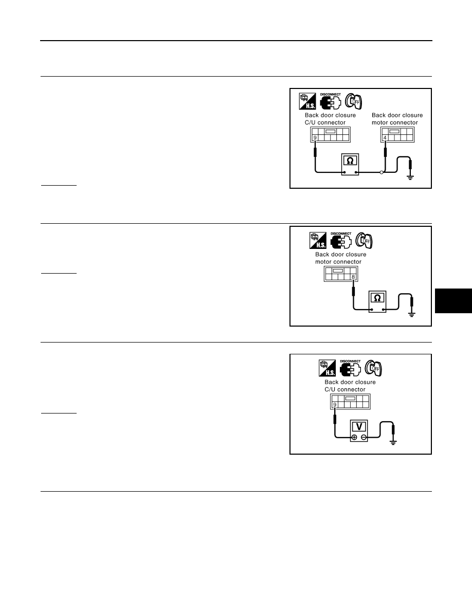
Check continuity between back door closure control unit con-
nector D106 terminal 9 and back door closure motor connector
D109 terminal 4.
3.
Check continuity between back door closure control unit con-
nector D106 terminal 9 and ground.
OK or NG
OK
>> GO TO 3.
NG
>> Repair or replace harness.
3.
CHECK GROUND CIRCUIT
Check continuity between back door closure motor connector D109
terminal 8 and ground.
OK or NG
OK
>> GO TO 4.
NG
>> Repair or replace harness.
4.
CHECK BACK DOOR CLOSURE CONTROL UNIT OUTPUT SIGNAL
1.
Connect back door closure control unit connector.
2.
Check voltage between back door closure control unit connector
D106 terminal 9 and ground.
OK or NG
OK
>> Replace back door lock assembly.
NG
>> Replace back door closure control unit.
Check Back Door Opener Switch (With Intelligent Key)
INFOID:0000000001327899
1.
CHECK BACK DOOR OPENER SWITCH SIGNAL
1.
Turn ignition switch OFF.
2.
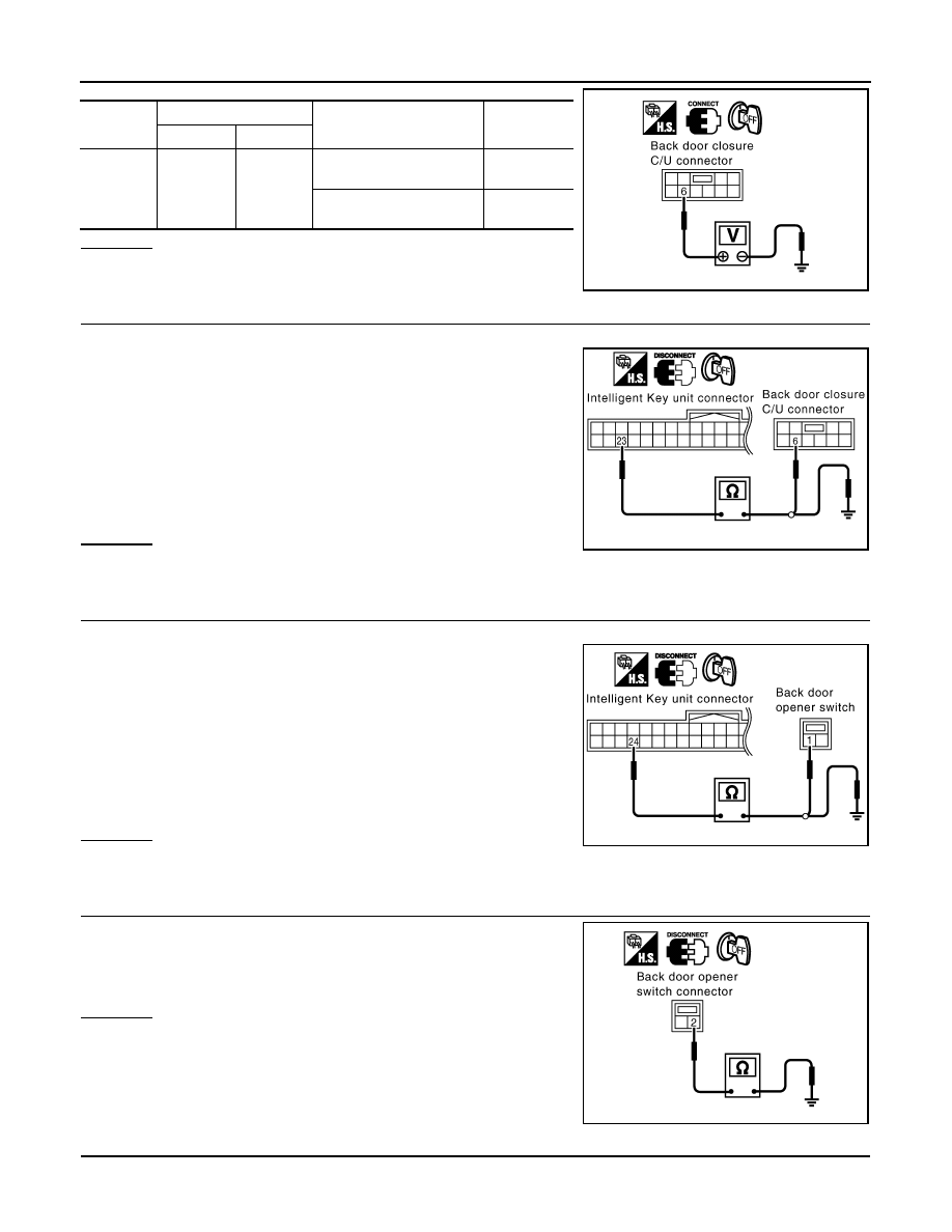
Check voltage between back door closure control unit connector and ground.
9 (P) – 4 (P)
: Continuity should exist.
9 (P) – Ground
: Continuity should not exist.
PIIA6176E
8 (B) – Ground
: Continuity should exist.
PIIA6170E
Back door is closed
9 (P) – Ground
: Battery voltage
PIIA6177E
BL-158
< SERVICE INFORMATION >
BACK DOOR AUTO CLOSURE SYSTEM
OK or NG
OK
>> Back door opener switch is OK.
NG
>> GO TO 2.
2.
CHECK HARNESS 1
1.
Disconnect Intelligent Key unit and back door closure control unit connector.
2.
Check continuity between Intelligent Key unit connector M34 ter-
minal 23 and back door closure control unit connector D106 ter-
minal 6.
3.
Check continuity between Intelligent Key unit connector M34 ter-
minal 23 and ground.
OK or NG
OK
>> GO TO 3.
NG
>> Replace or repair malfunction harness.
3.
CHECK HARNESS 2
1.
Disconnect Intelligent Key unit and back door opener switch connector.
2.
Check continuity between Intelligent Key unit connector M34 ter-
minal 24 and back door opener switch connector D112 terminal
1.
3.
Check continuity between Intelligent Key unit connector M34 ter-
minal 24 and ground.
OK or NG
OK
>> GO TO 4.
NG
>> Replace or repair malfunction harness.
4.
CHECK BACK DOOR OPENER SWITCH GROUND CIRCUIT
Check continuity between back door opener switch connector D112
terminal 2 and ground.
OK or NG
OK
>> GO TO 5.
NG
>> Repair or replace harness.
5.
CHECK BACK DOOR OPENER SWITCH
Connector
Terminals (Wire color)
Condition
Voltage (V)
(Approx.)
(+)
(-)
D106
6 (LG)
Ground
Back door opener switch
: ON
0
Back door opener switch
: OFF
5
PIIA6178E
23 (L/Y) – 6 (LG)
: Continuity should exist.
23 (L/Y) - Ground
: Continuity should not exist.
PIIB0216E
24 (P) – 1 (Y)
: Continuity should exist.
24 (P) - Ground
: Continuity should not exist.
PIIB1384E
2 (B) – Ground
: Continuity should exist.
PIIA6180E
Нет комментариевНе стесняйтесь поделиться с нами вашим ценным мнением.
Текст